2 Installation
K0443 Revision A 2 - 6 [EN] English
Note: (Ref: Section 6, Reference and Specification) for details of other system components.
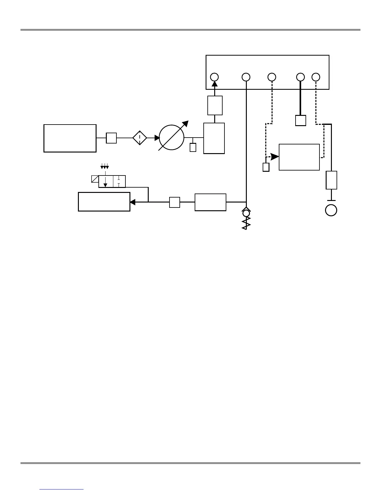
Figure 2-4, Pneumatic Connections with vacuum supply
Note: The PACE option IO-VAC-SYS Vacuum System Check Valve Kit should be used in the
vacuum line mounted near the PACE CM -ve port to exhaust most HP gas directly to
atmosphere. The vacuum buffer volume needs to be rated at least to the highest
system pressure.
Note: (Ref: Section 6, Reference and Specification) for details of other system components
1) Pressure source 2) Conditioner 3) Filter
4) Regulate to between 110% full-scale and MWP 5) Diffuser*
6) Unit under test 7) Optional reservoir † 8) Protection device
9) Optional differential connection 10) Oil mist trap
11) Vacuum source 12) Normally open electrical release valve 13) Check valve **
14) Manual external vent valves a) Atmosphere
 Loading...