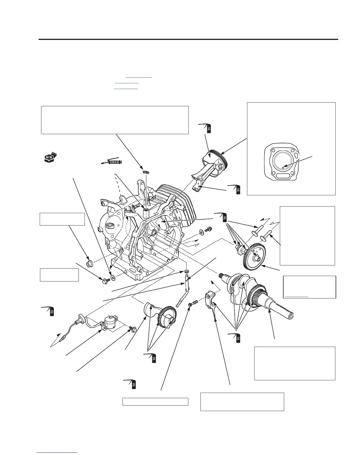
CRANKCASE
CRANKSHAFT/BALANCER WEIGHT/PISTON
REMOVAL/INSTALLATION
Remove the following parts:
– Cylinder head
(page 12-3)
– Fuel tank (page 6-3)
– Flywheel (page 8-7)
LOCK PIN (10 mm)
PISTON
WASHER (8.2 x 17 x 0.8 mm)
VALVE LIFTER
CAMSHAFT
CRANKSHAFT
CONNECTING ROD LOWER
CONNECTING ROD BOLT (2)
BALANCER
WEIGHT
GOVERNOR ARM SHAFT
DRAIN PLUG
BOLT (2)
DRAIN PLUG
WASHER (12 mm) (2)
Viewed from cylinder head side
MARK
22.5 N·m (2.25
kgf·m, 17 lbf·ft)
14 N·m (1.4 kgf·m, 10 lbf·ft)
(Apply oil to the threads
and seating surface)
OIL LEVEL SW
OIL LEVEL
SWITCH NUT
(10 mm)
10 N·m (1.0 kgf·m,
7 lbf·ft)
GROOVE
BOLT (6 X 12 mm) (2)
REMOVAL:
When removing the
valve lifters, mark so
that the intake and
exhaust sides can be
distinguished.
INSTALLATION:
Attach the valve lifters
to the cylinder barrel
immediately before
installing the camshaft.
INSTALLATION:
Before installing the crankshaft,
check the oil seal of the cylinder
barrel for damage or hardening.
Be careful not to damage the oil
seal when installing the crankshaft.
INSTALLATION:
Set the connecting rod lower with
the oil dipper toward the camshaft.
INSTALLATION:
Install the piston to the cylinder
barrel with the mark on the piston
head toward the push rod hole of the
cylinder head.
INSTALLATION:
Install the lock pin immediately after installing the governor arm
shaft in the direction as shown.
The 10 mm lock pin must be installed with the straight side of the
10 mm lock pin against the groove of the governor arm shaft.
See BALANCER
WEIGHT/CAMSHAFT
INSTALLATION on
page 13-6.
(Oil seal lip)
 Loading...