GOVERNOR SYSTEM
FIXED THROTTLE OPERATION TYPE
Remove the following parts.
– Air cleaner (page 6-5)
– Muffler (page 14-2)
– Fuel tank (page 6-3)
– Tube clamp (page 6-8) (If equipped)
Installation is in the reverse of removal.
Adjust the maximum speed (page 7-8).
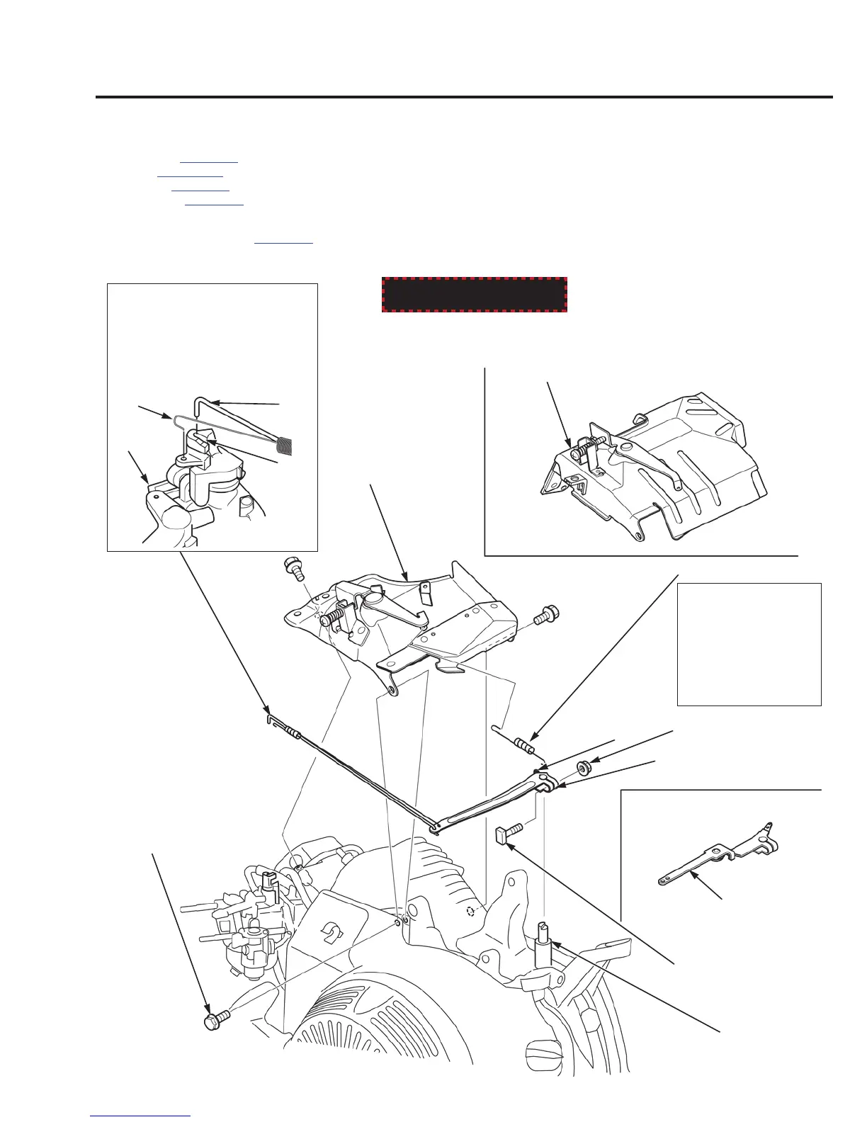
INSTALLATION:
Install with the long end
of the spring toward the
control base assy.
Hook the governor spring
to the outer hole of the
governor arm.
CONTROL BASE ASSY.
GOVERNOR ARM
GOVERNOR ARM
BOLT
NUT (6 mm)
BOLT (6 x 12 mm) (3)
(If equipped)
GOVERNOR SPRING
GOVERNOR ARM
SHAFT
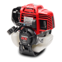
REMOVAL/INSTALLATION:
Pull the carburetor assy. (1) out to a
point where the groove (2) of the
throttle arm lines up with the
governor rod (3), and then lift the
governor rod out of the hole of the
throttle arm and unhook the throttle
return spring (4).
GOVERNOR ROD/THROTTLE
RETURN SPRING
(3)
(2)
(1)
(4)
CONTROL BASE ASSY.
(If equipped)
(If equipped)
GOVERNOR ARM
(If equipped)
OUTER HOLE