WIRING DIAGRAMS
WIRING DIAGRAMS
HOW TO READ A WIRING DIAGRAM & RELATED INFORMATION
This section explains how to use the connector drawings, symbols, and wiring diagram, when troubleshooting.
HOW TO READ CONNECTOR DRAWINGS
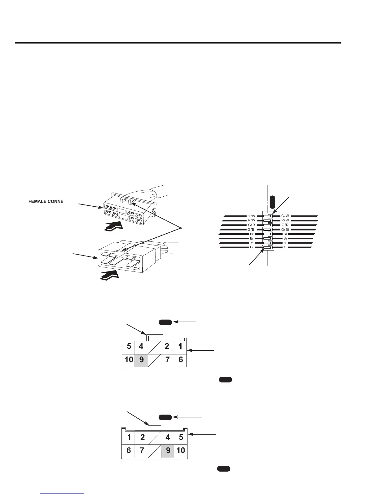
Connector drawings show the terminal number, pin arrangement, number of pins, and the type of the terminal (male or female).
Both the male and female connectors are shown for the common connectors, while only the main wire harness side connectors are
shown for the dedicated connectors.
Double frame connectors represent male connectors and the single frame connectors represent female connectors.
The gender of the connector is determined by the type of terminals the connector contains. Male connectors have male terminals.
Female connectors have female terminals. Typically, the smaller plastic plastic shell of a female connector inserts inside the larger
plastic shell of a male connector when they are joined.
Terminals in a female connector are numbered from left to right, top to bottom looking at the wire side. Terminals in a male
connector are numbered from left to right, top to bottom looking at the terminal side.
Both the male and female connectors are shown by viewing them from the terminal side.
3
9 1 25 4 6 7
10
G
G/W
G/R
G/Bl
R/W
Br
Br
Y
G
G/W
G/R
G/Bl
R/W
Br
Br
Y
4 12
10
9 7 6
5
10
976
5
421
FEMALE CONNECTOR
(Female terminals)
MALE CONNECTOR
(Male terminals)
LOCKS
VIEWING DIRECTION
VIEWING DIRECTION
FEMALE CONNECTOR DRAWING
(SINGLE FRAME)
Female connector viewed from the
terminal side.
MALE CONNECTOR DRAWING
(DOUBLE FRAME)
Male connector viewed from the
terminal side.
TERMINAL No.
This drawing shows the No. 9 terminal of the male connector
with the lock of the connector UP.
3
MALE LOCK
CONNECTOR No.
TERMINAL ARRANGEMENT
This drawing shows the No. 9 terminal of the female connector
with the lock of the connector UP.
3
FEMALE LOCK
MALE CONNECTOR
(Male terminals)
FEMALE CONNECTOR
(Female terminals)
3
3
CONNECTOR No.
3
 Loading...