WIRING DIAGRAMS
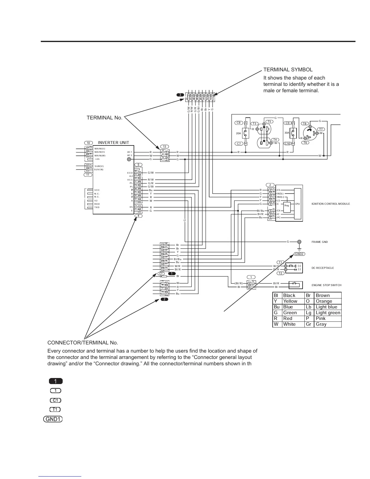
HOW TO READ A WIRING DIAGRAM
1
2
C1
4
5
GND2
T1
T2
1
2
13
10
11
3
C8
C7
1 2
5
3 4 6
7
10
9 1 2 5 4 6 7
10
1
2 3
12 1 2 3 4
9 1 2 5 3 4 8 7
10
1 2
92 5 4 7
10
12 3 4
1 6
1 2
C10
C9
T8
T6
T7
T5
T3
T4
G
G/W
G/R
G/Bl
R/W
Br
Br
Y
G
G
R
R
R R
W
W
W
R
Bl/R
Bl/Bu
G
G
Y
Y
Bu
W/R
Bl/R
G
Bl/R
Bl
Br
Br
G
(Bl/R)
Bl/Bu
Y
W/R
Bl/R
Bu
Bl
Bl
Y
Bu
R
W
G
R
W
G
R
W
G
G/W
G/R
G/Bl
R/W
Y
Bu
R
R
W
G
MAIN( U)
MAIN( V)
SUB(V )
SUV(N )
MAIN( W)
-vdc
AC1
AC2
VCC
VCC
N.C.
N.C.
RXD
TXD
V2
ECO
HZ
PL
PL
B
B
A
A
ES
E
ES
EX
IC
CPU
PC
E
Reg
LS
IND(-)
IND(+)
INVERTER UNIT
IGNITION CONTROL MODULE
FRAME GND
ENGINE STOP SWITCH
30A
20A
DC RECEPTACLE
(+)
(-)
Bl Black Br Brown
Y Yellow O Orange
Bu Blue Lb Light blue
G Green Lg Light green
R Red P Pink
W White Gr Gray
TERMINAL SYMBOL
It shows the shape of each
terminal to identify whether it is a
male or female terminal.
TERMINAL No.
CONNECTOR/TERMINAL No.
Every connector and terminal has a number to help the users find the location and shape of
the connector and the terminal arrangement by referring to the “Connector general layout
drawing” and/or the “Connector drawing.” All the connector/terminal numbers shown in this
Service Manual are either of those shown in this section.
Indicates a ground.
(Circled GND followed with
No. in white background)
: Connector that relays from a harness to a harness (Circled No. in black background)
: Connector that connects to electrical equipment (Circled No. in white background)
: Connector (Circled C followed with No. in white background)
: Terminal (Circled T followed with No. in white background)
: Ground (Circled GND followed with No. in white background)
 Loading...