UDACT Instruction Manual — P/N 50050:M 12/18/2009 11
Controls and Indicators Overview
• Troubleshoot mode converts keypad to DTMF touchpad
• Individual LEDs for:
– Power
– EIA-485 loss
– Manual Test
– Kissoff
– Comm Fail
– Primary Line Seize
– Secondary Line Seize
• Open collector relay driver for Total Communication Failure or UDACT trouble.
• Real Time Clock
• Simple EIA-485 interface to host panel
• Maximum of 14 point trouble messages transmitted per hour.
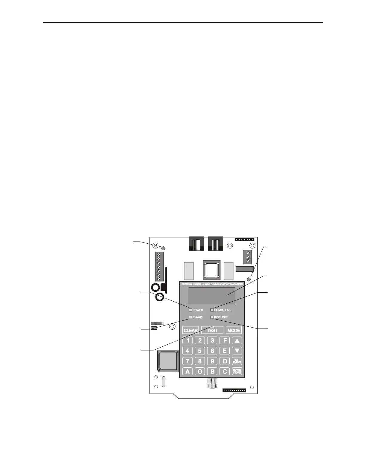
1.6 Controls and Indicators
The following membrane type switches are provided on the front panel of the UDACT:
Displays are as shown below:
Figure 1.1 Controls and Indicators
CLEAR TEST MODE
Up Arrow Down Arrow Digits 0 - 9
1st EVENT ENTER/STORE Letters A -F
UDACT-01.wmf
COMM. FAIL
Yellow LED
KISS OFF
Green LED
EIA-485
Yellow LED
POWER
Green LED
Four, Seven
Segment Displays
Primary Active -
Red LED
(phone line)
Secondary Active -
Red LED
(phone line)
TEST
Green LED

 Loading...