1-11
Introducing the HP 2920 Switches
Fronts of the Switches
LED Mode Select Button and Indicator LEDs
The operation of the Mode LED is controlled by the LED Mode select button,
and the current setting is indicated by the LED Mode indicator LEDs near the
button. Press the button to step from one view mode to the next. See the LED
information in Table 1-3 on page 1-7 for standalone switches, and in
Table 1-4 on page 1-10 for stacked switches.
Stacking
Notes:
■ For HP 2920 switches that are in a stack, the Mode select button on every
switch in the stack controls the LED mode for all the switches in the stack.
■ If there is a combination of PoE/PoE+ switches and non-PoE switches in
the stack, when any of the Mode select buttons is pressed to put the stack
into PoE mode, the non-PoE switches indicate no PoE support by not
illuminating any of the Mode indicator LEDs or any of the port LEDs.
■ If any of the switches in the stack are configured with the Save Power
LED feature, then the default LED Mode for the whole stack becomes the
Save Power display (all LED Mode indicator LEDs are off), but only the
stack members on which that feature is configured display the other
characteristics of that feature (all LEDs Off except for the Power LED).
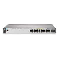
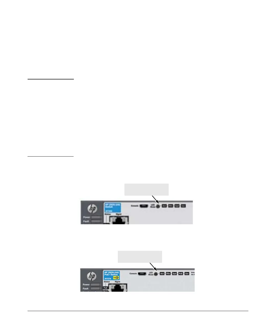
Figure 1-5. Example of Indicator LEDs on a non-PoE HP 2920 Switch
Figure 1-6. Example of Indicator LEDs on a PoE/PoE+ HP 2920 Switch
LED Mode select button
and indicator LEDs
LED Mode select button
and indicator LEDs
 Loading...