2-28
Installing the Switch
Sample Network Topologies
Sample Network Topologies
This section shows a few sample network topologies in which the switch is
implemented. For more topology information, visit the product’s Web site at
www.hp.com/networking/support.
The switch is designed to be used primarily as a desktop switch to which end
nodes, printers and other peripherals, and servers are directly connected, as
shown in the following illustration. Notice that the end node devices are
connected to the switch by straight-through or crossover twisted-pair cables.
Either cable type can be used because of the “Auto MDI-X” features on the
switch.
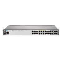
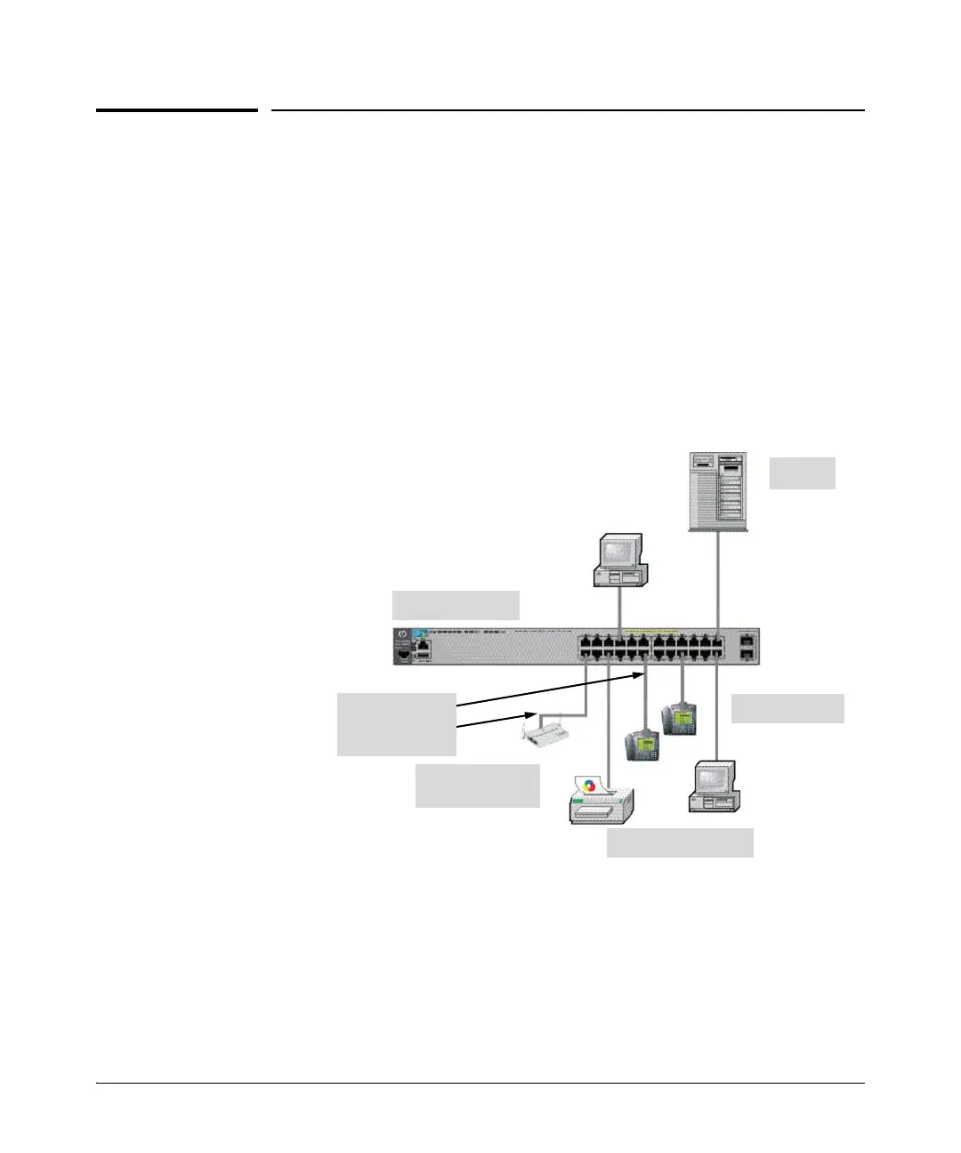
Figure 2-24. Example as a Desktop Switch Implementing PoE/PoE+
This illustration is an example of the switch being configured to supply PoE/
PoE+ power to end devices such as IP telephones and wireless access points
(WAPs).
The end node devices are connected to the switch by straight-through or
crossover twisted-pair cables. Either cable type can be used because of the
“Auto MDI-X” features on the switch.
Server
PCs and peripherals
HP 2920-24G Switch
Wireless Access
Point
IP Telephones
Twisted-pair
straight-through or
crossover cables
 Loading...