2-20
Installing the Switch
Installation Procedures
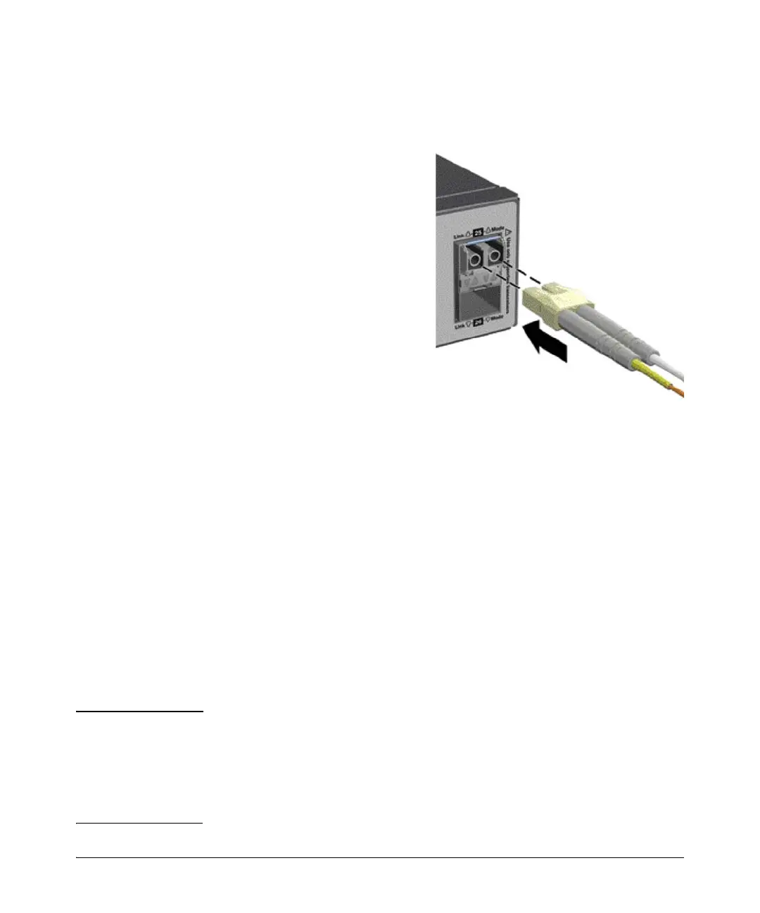
Connecting a fiber cable
To connect:
1. Remove the dust covers from
the cable connectors and the
port.
2. Aligning the notches on the
cable connectors with the slots
of the port, press the cable
connector into the port until it
snaps into place.
If the Link LED does not go on
when the network cable is
connected to the port, see
“Diagnosing with the LEDs” on
page 5-4, in chapter 5,
“Troubleshooting”.
To disconnect:
Pull the cable connector straight
out.
10. (Optional) Connect a Management Console
The switch has a full-featured, easy to use console interface for performing
switch management tasks including:
■ monitor switch and port status and observe network activity statistics
■ modify the switch’s configuration to optimize switch performance,
enhance network traffic control, and improve network security
■ read the event log and access diagnostic tools to help in troubleshooting
■ download new software to the switch
■ add passwords to control access to the switch from the console, web
browser interface, and network management stations
Important After you install and power up the switch, to use a networked (in-band or out-
of-band) connection to manage the switch, you can use the out-of-band
console connection to minimally configure the switch with an IP address and
subnet mask. By default, the switch is configured to acquire an IP address via
DHCP. See “Minimal Configuration Through the Console Port Connection” on
page 3-2 for more information.
Figure 2-17. Connecting fiber optic cable
 Loading...