101
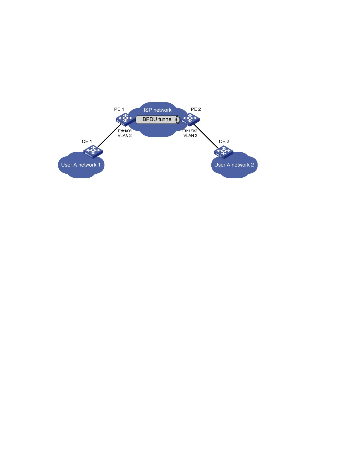
• All ports that connect service provider devices and customer devices are access ports and
belong to VLAN 2. All ports that interconnect service provider devices are trunk ports and allow
packets of any VLAN to pass through.
• MSTP is enabled on User A’s network.
After the configuration, CE 1 and CE 2 must implement consistent spanning tree calculation across
the service provider network, and the destination multicast MAC address carried in BPDUs must be
0x0100-0CCD-CDD0.
Figure 30 Network diagram
Configuration procedure
1. Configure PE 1:
# Configure the destination multicast MAC address for BPDUs as 0x0100-0CCD-CDD0.
<PE1> system-view
[PE1] bpdu-tunnel tunnel-dmac 0100-0ccd-cdd0
# Create VLAN 2 and assign Ethernet 1/0/1 to VLAN 2.
[PE1] vlan 2
[PE1-vlan2] quit
[PE1] interface ethernet 1/0/1
[PE1-Ethernet1/0/1] port access vlan 2
# Disable STP on Ethernet 1/0/1, and then enable BPDU tunneling for STP on it.
[PE1-Ethernet1/0/1] undo stp enable
[PE1-Ethernet1/0/1] bpdu-tunnel dot1q stp
2. Configure PE 2:
# Configure the destination multicast MAC address for BPDUs as 0x0100-0CCD-CDD0.
<PE2> system-view
[PE2] bpdu-tunnel tunnel-dmac 0100-0ccd-cdd0
# Create VLAN 2 and assign Ethernet 1/0/2 to VLAN 2.
[PE2] vlan 2
[PE2-vlan2] quit
[PE2] interface ethernet 1/0/2
[PE2-Ethernet1/0/2] port access vlan 2
# Disable STP on Ethernet 1/0/2, and then enable BPDU tunneling for STP on it.
[PE2-Ethernet1/0/2] undo stp enable
[PE2-Ethernet1/0/2] bpdu-tunnel dot1q stp