169
# Enable portal authentication on the interface connecting Switch B.
[SwitchA] interface vlan-interface 4
[SwitchA–Vlan-interface4] portal server newpt method layer3
[SwitchA–Vlan-interface4] quit
On Switch B, configure a default route to subnet 192.168.0.0/24, setting the next hop as 20.20.20.1.
(Details not shown.)
Configuring portal stateful failover
Network requirements
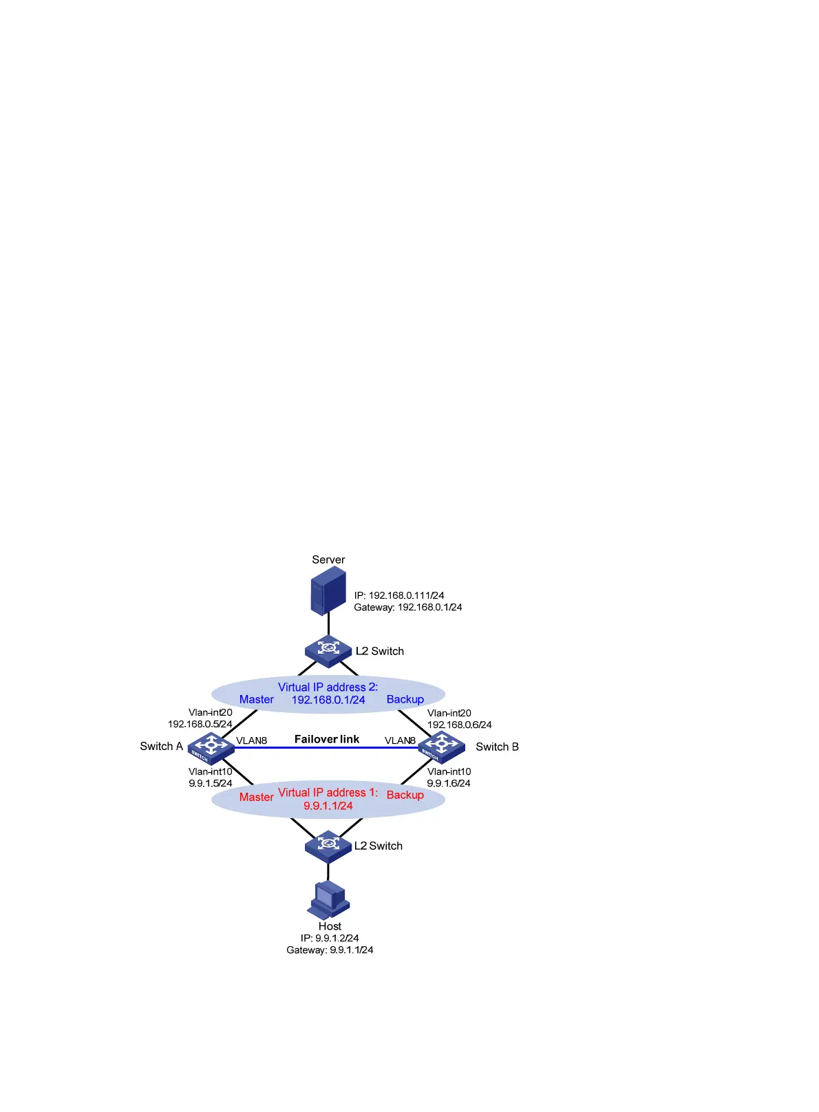
As shown in Figure 56, a failover link is present between Switch A and Switch B. Both Switch A and
Switch B support portal authentication. Configure stateful failover between Switch A and Switch B to
support portal service backup and use VRRP to implement traffic switchover between the switches. More
specifically,
• When Switch A works normally, Host accesses Switch A for portal authentication before accessing
the Internet; when Switch A fails, Host accesses the Internet through Switch B. The VRRP
uplink/downlink detection mechanism is used to ensure non-stop traffic forwarding.
• Use the RADIUS server as the authentication/accounting server. In this example, Server takes the
responsibilities of the portal server and the RADIUS server.
• Switch A and Switch B use the failover link to transmit stateful failover related packets and specify
VLAN 8 on the switches as the VLAN dedicated for stateful failover related packets.
Figure 56 Network diagram
Configure IP addresses for the host, server, and switches as shown in Figure 56 and make sure that they
can reach to each other.
 Loading...