391
Ste
Command
Remarks
1. Enter system view.
system-view N/A
2. Enter Layer 2 Ethernet interface
view/Layer 2 aggregate interface
view.
interface interface-type
interface-number
N/A
3. Configure an ARP filtering entry.
arp filter binding ip-address
mac-address
Not configured by default
Configuration example
Network requirements
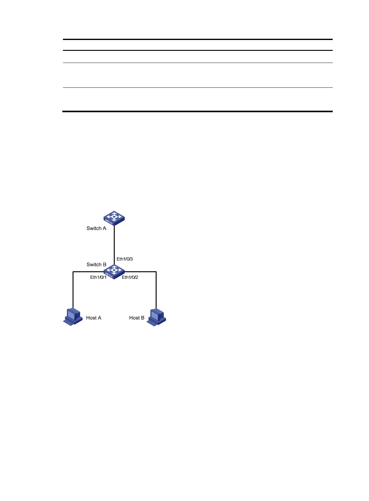
As shown in Figure 122, the IP and MAC addresses of Host A are 10.1.1.2 and 000f-e349-1233. The IP
and MAC addresses of Host B are 10.1.1.3 and 000f-e349-1234.
Configure ARP filtering on Ethernet 1/0/1 and Ethernet 1/0/2 of Switch B to permit specific ARP
packets only.
Figure 122 Network diagram
Configuration procedure
# Configure ARP filtering on Switch B.
<SwitchB> system-view
[SwitchB] interface ethernet 1/0/1
[SwitchB-Ethernet1/0/1] arp filter binding 10.1.1.2 000f-e349-1233
[SwitchB-Ethernet1/0/1] quit
[SwitchB] interface ethernet 1/0/2
[SwitchB-Ethernet1/0/2] arp filter binding 10.1.1.3 000f-e349-1234
After the configuration is complete, Ethernet 1/0/1 will permit incoming ARP packets with sender IP and
MAC addresses as 10.1.1.2 and 000f-e349-1233, and discard other ARP packets. Ethernet 1/0/2 will
permit incoming ARP packets with sender IP and MAC addresses as 10.1.1.9 and 000f-e349-1233 and
discard other ARP packets. ARP packets from Host A are permitted, but those from Host B are discarded.
 Loading...