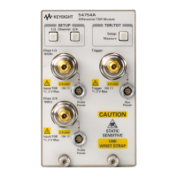
Single-ended TDR Measurements
Single-ended TDR Features
7-3
Single-ended TDR Features
The HP 54753A and HP 54754A TDR plug-in modules are both capable of
performing singe-ended TDR measurements. These measurements include
characterizing microstrip lines, PC board traces, and coaxial cables. Because
TDR measurements are complex, the TDR plug-in modules have several
features which make measurements easier.
The Preset TDR/TDT Feature
The Preset TDR/TDT feature prepares the oscilloscope for making Time Domain
Reflectometry (TDR) and Time Domain Transmission (TDT) measurements by
automatically setting several menu fields. The Preset TDR/TDT feature appears
in the TDR/TDT Setup menu once a stimulus has been selected.
TDR Establish Normalization and Reference Plane Feature
This feature performs the following:
• Establishes the Reference Plane.
• Measures the negative going step reflected from a short.
• Builds a normalization filter.
• Measures the response to a 50 ohm terminator.
The Reference Plane is defined as the point in time that coincides with the 50%
point of the negative going step that is reflected from a short connected to a 50
ohm line. Once the Reference Plane is established, cursor measurements can
be made with respect to this point in time rather than to the trigger point.
Typically, the short is connected at the end of a cable which will be connected
to the device under test. This effectively establishes this end of the cable as
the Reference Plane.
The next stage in the Establish Normalization and Reference Plane process
involves measuring the negative going step reflected from the short at the end
of the cable. This allows the oscilloscope to base the percent reflection and
ohms measurements on the actual measured step height rather than the
nominal step height of 200 mV.
Also, from this information, the oscilloscope builds a normalization filter which
can be applied to any reflected signal. When applied to the short, the filter
produces a step which has no preshoot or overshoot and has an impulse
response which is approximately Gaussian. The risetime of this filtered step
can be selected when making TDR measurements of systems using a range of
risetimes. This filter removes any losses or discontinuities from the TDR plug-

