TDR Fundamentals
Step Reflection Testing
9-6
by the phase relationship between incident and reflected waves. The ratio of
the maximum and minimum values of this voltage is called the voltage standing
wave ratio, σ, and is related to the reflection coefficient by the equation
As has been said, either of the above coefficients can be measured with
presently available test equipment. But the value of the SWR measurement is
limited. Again, if a system consists of a connector, a short transmission line and
a load, the measured standing wave ratio indicates only the overall quality of
the system. It does not tell which of the system components is causing the
reflection. It does not tell if the reflection from one component is of such a
phase as to cancel the reflection from another. The engineer must make detailed
measurements at many frequencies before he can know what must be done to
improve the broadband transmission quality of the system.
Step Reflection Testing
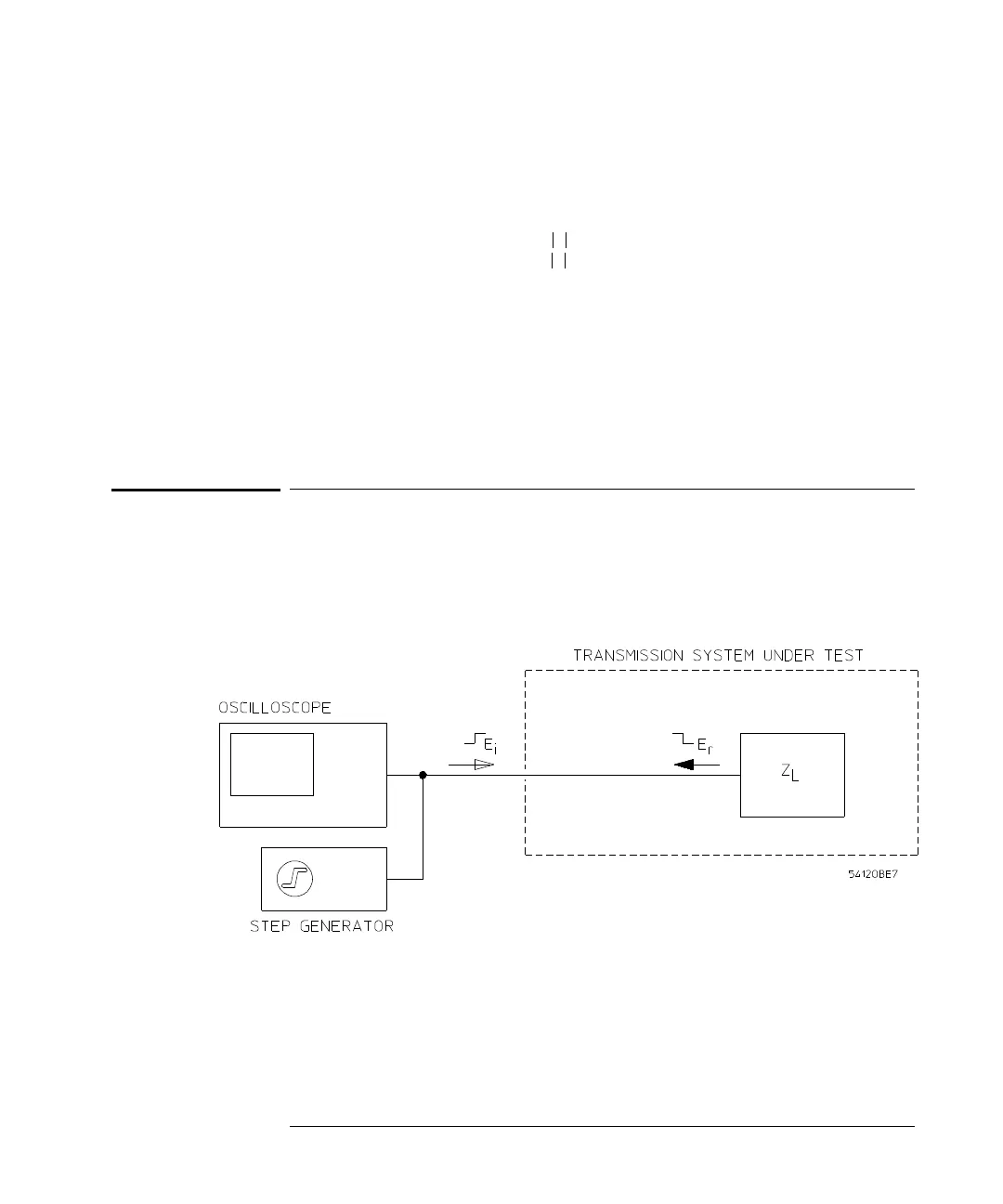
A time domain reflectometer setup is shown in Figure 9-3.
Figure 9-3
A Time Domain Reflectometer
The step generator produces a positive-going incident wave that is applied to
the transmission system under test. The step travels down the transmission
line at the velocity of propagation of the line. If the load impedance is equal to
σ
1
ρ
+
1
ρ
–
---------------=

 Loading...


