TDR Fundamentals
Step Reflection Testing
9-7
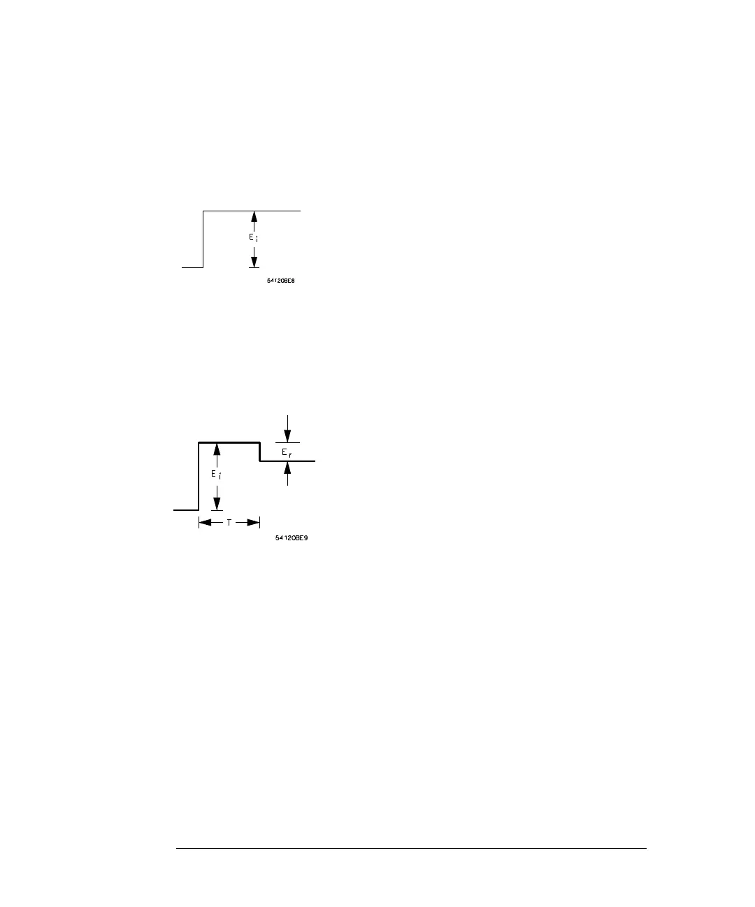
the characteristic impedance of the line no wave is reflected and all that will be
seen on the oscilloscope is the incident voltage step recorded as the wave passes
the point on the line monitored by the oscilloscope. Refer to Figure 9-4.
Figure 9-4
Oscilloscope Display When E
r
= 0
If a mismatch exists at the load, part of the incident wave is reflected. The
reflected voltage wave will appear on the oscilloscope display algebraically
added to the incident wave. Refer to Figure 9-5.
Figure 9-5
Oscilloscope Display When E
r
≠
0
Locating Mismatches
The reflected wave is readily identified since it is separated in time from the
incident wave. This time is also valuable in determining the length of the
transmission system from the monitoring point to the mismatch. Letting D
denote this length:
wherev
p
= velocity of propagation
T = transit time from monitoring point to the mismatch and
back again, as measured on the oscilloscope (Figure 9-5)
Dv
p
T
2
---
•
v
p
T
2
--------==

 Loading...


