TDR Fundamentals
Propagation on a Transmission Line
9-4
Propagation on a Transmission Line
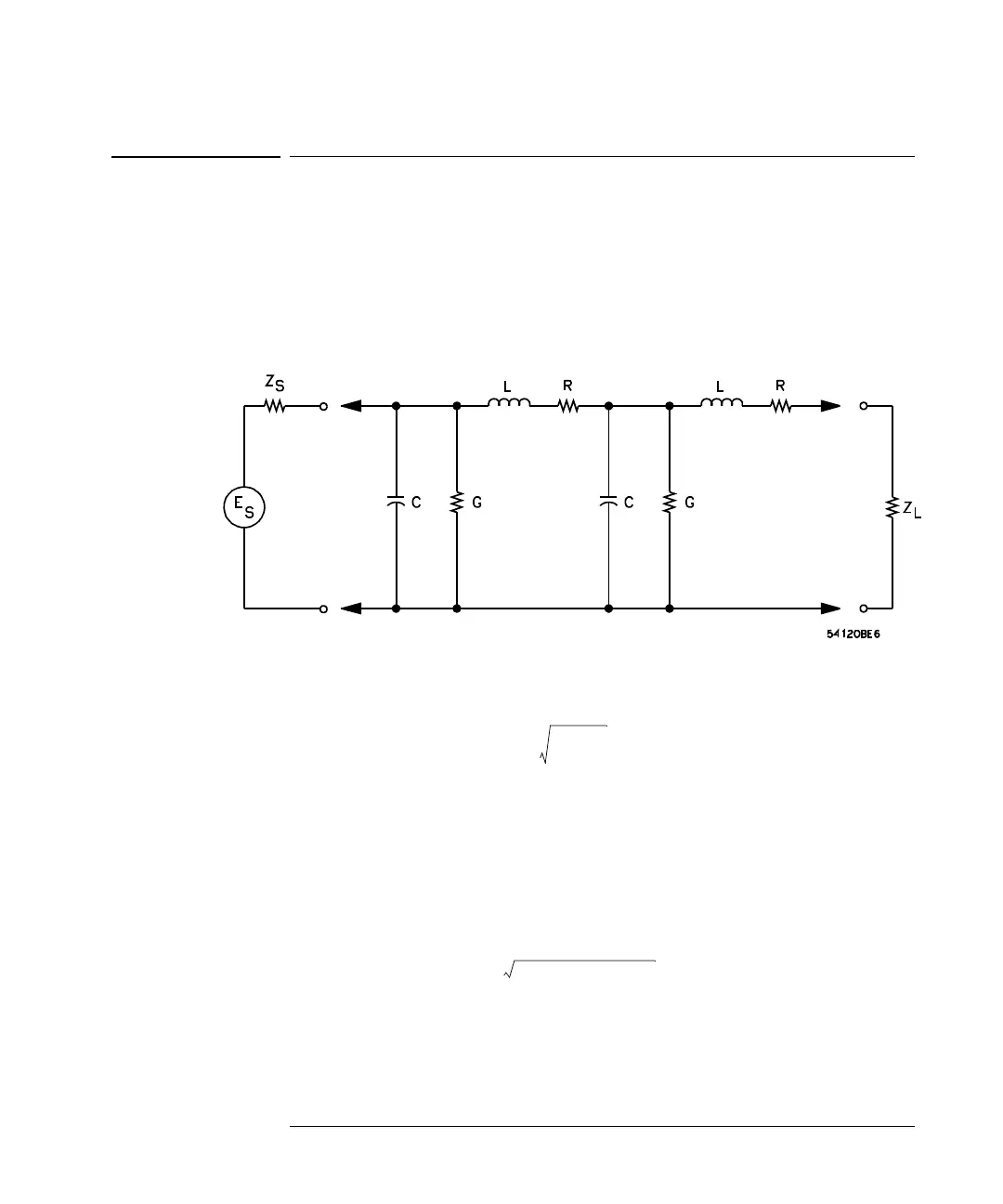
The classical transmission line is assumed to consist of a continuous structure
of resistors (R), inductors (L) and capacitors (C), as shown in Figure 9-2. By
studying this equivalent circuit, several characteristics of the transmission line
can be determined.
Figure 9-2
The Classical Model for a Transmission Line.
If the line is infinitely long and R, L, G, and C are defined per unit length, then
where Z
o
is the characteristic impedance of the line. A voltage introduced at
the generator will require a finite time to travel down the line to a point x. The
phase of the voltage moving down the line will lag behind the voltage introduced
at the generator by an amount β per unit length. Furthermore, the voltage will
be attenuated by an amount α per unit length by the series resistance and shunt
conductance of the line. The phase shift and attenuation are defined by the
propagation constant γ,where
where α = attenuation in nepers per unit length
β = phase shift in radians per unit length
Z
in
Z
o
Rj
ω
L+
Gj
ω
L+
--------------------==
γα
j
β
+ Rj
ω
L+
()
Gj
ω
C+
()
==

 Loading...


