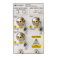
Differential TDR Measurements
Differential TDR Features
8-4
channel
Skew
control moves the position of the acquired waveform. Both
controls are needed to properly deskew the TDR step generators for differential
TDR.
Differential TDR measurements require two cables to be connected from the
TDR channels to the device under test. These cables should be good quality
cables of equal length (within 1 ns delay of each other). The procedure for
deskewing the differential TDR to the ends of the cables is as follows:
• Insure that the open reflection of each TDR channel overlay each other with
no cables attached. If they are not, either do a plug-in calibration or adjust
the
TDR Skew
so they overlay each other.
• Attach the cables. Notice that unless the cables are matched in electrical
length, the open reflections now do not overlay each other. Using the ∆Time
auto measurement or manual markers, measure the delta time (skew)
between the TDR channels.
• Now go to the channel
Skew
control for the channel that is more to the right
on the screen. Adjust this control until the skew between the TDR channels
is reduced to half of what it was initially.
• Now use one of the
TDR Skew
controls from either TDR channel to reduce
the remaining skew to approximately 0.
The TDR step generators are now deskewed to the ends of the cables. The open
reflections off the end of the cables should overlay each other. Note that the
incident steps of the two channels probably do not overlay each other. They
won't unless the cables are the same electrical length. This is not a problem
because only the reflected signals need to be deskewed. The system in now
ready to make differential TDR measurements. If differential TDT
measurements are to be made, an additional deskew of the destination channels
needs to be done for TDT.
• Connect an additional two cables to the two TDT destination channels.
• Using some SMA or 3.5 mm F-F adaptors, connect the TDR channels to the
TDT channels. The transmitted steps should now be seen on the TDT
destination channels.
• Unless the electrical lengths of the two transmission paths happen to be
identical, the transmitted steps will not overlay each other.
• Now go to the channel
Skew
control for the channel that is more to the right
on the screen. Adjust this control until the skew between the TDT channels
is reduced to approximately 0.
The TDT paths are now deskewed. The device under test can now be connected
to the 4 cables, and the transmitted response observed.

 Loading...