 Loading...
Do you have a question about the Huawei TaiShan 200 2280 and is the answer not in the manual?
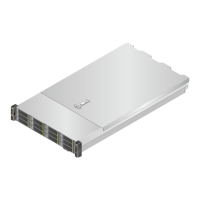
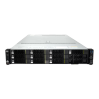
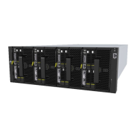
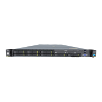
Describes the physical structure, components, and specifications of the server.
Specifies the target audience for this document.
Defines the meaning of symbols used throughout the document.
Describes components located on the front panel of the server.
Details the indicators and buttons present on the front panel.
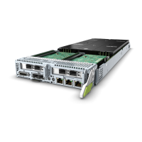
Identifies and describes components on the rear panel of the server.
Lists and explains the indicators found on the rear panel.
Shows the indicators on the FlexIO cards.
Provides information on drive slot numbering and indicators.
Illustrates the connectors on the drive backplane.
Details the ports on the mainboard and iBMC card.
Covers DIMM slots and installation rules.
Describes riser cards and specifications for PCIe slots.
Shows the server's fan modules and their function.
Illustrates cabling for left and right mounting ears in Expander mode.
Illustrates cabling for left and right mounting ears in Pass-Through mode.
Illustrates cabling for left and right mounting ears in Expander mode.
Illustrates cabling for left and right mounting ears with mixed drive types.
Illustrates cabling for left and right mounting ears in Pass-Through mode.
Illustrates internal cabling for NVMe SSDs in I/O module 3.
Details technical specifications based on processor models.
Specifies operating environment requirements like temperature and humidity.
Details the server's physical dimensions and weight.
Provides specifications and recommendations for Power Supply Units (PSUs).
Lists the necessary tools for performing maintenance procedures.
Details essential measures for protecting components from ESD damage.
Explains the meaning of various safety symbols and labels.
Covers fundamental operations like powering the server on and off.
Explains the procedure for removing and installing the front bezel.
Provides procedures for removing and installing server drives.
Details the process for replacing AC and DC Power Supply Units.
Explains how to remove and install the server's chassis cover.
Details the procedure for removing and installing the air duct.
Explains how to remove and install a fan module.
Details the process for removing and installing riser modules.
Explains how to remove and install PCIe cards on riser modules.
Details the procedure for removing and installing the system battery.
Explains how to remove and install the screw-in RAID controller card.
Details the procedure for removing and installing the supercapacitor.
Explains how to remove and install DIMMs.
Details the procedure for removing and installing FlexIO cards.
Explains how to remove and install the front drive backplane.
Provides procedures for rear drive module replacement.
Explains how to remove and install the left mounting ear plate.
Explains how to remove and install the right mounting ear plate.
Details the process of removing and installing the server mainboard.
Describes the systematic approach to identify and fix faults.
Emphasizes collecting logs for effective fault diagnosis.
Highlights the use of rules and tools for fault analysis.
Covers downloading and applying software/firmware updates.
Focuses on proactive measures to prevent system issues.
Provides information on accessing technical support resources.
Lists software tools required for routine server maintenance.
Explains how to find the server's management network port IP address.
Guides users on accessing the iBMC Web Interface.
Details how to connect to the iBMC Command Line Interface.
Explains how to access the server's remote virtual console.
Provides instructions for serial port login using PuTTY.
Details remote login via network port using PuTTY.
Explains methods to find the server's CPU processor model.
Defines abbreviations for spare part types and their application scenarios.
Provides a basic overview of the BIOS functionality and its role.
Describes the features and functions of the iBMC system.
Defines technical terms and acronyms used in the document.
Lists common acronyms and their full forms.