EasyManua.ls Logo

IBM 5100 User Manual

IBM 5100
389 pages
To Next Page IconTo Next Page
To Previous Page IconTo Previous Page
Page #256 background imageLoading...
Page #256 background image
Logic Symbol Legend
GENERAh
LOGIC INFORMATION
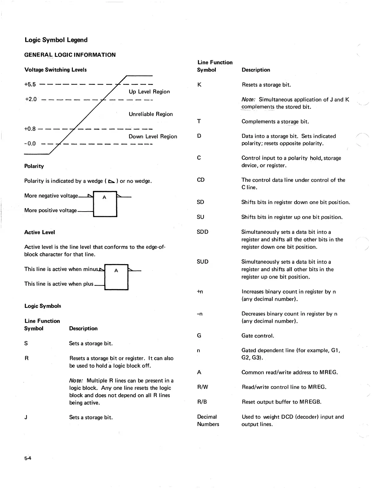
Voltage Switching Levels
+5.5
--
---
-
---
Up
Level
Region
+2.0
....,.------
Unreliable Region
+0.8 -
---
Down
Level
Region
Polarity
Polarity
is
indicated by a wedge ( t::...)
or
no wedge.
More negative
VOltage~
A I
More positive voltage
-----
Active Level
Active level
is
the
line level
that
conforms
to
the
edge-of-
block character for
that
line.
This line
is
active when
minus~
This line
is
active when
PIUS-U
Logic Symbols
Line Function
Symbol Description
S Sets a storage bit.
R Resets a storage
bit
or
register. I t can also
be
used
to
hold a logic block off.
J
5-4
Note: Multiple R lines can
be
present
in
a
logic block.
Anyone
line resets the logic
block and does
not
depend on
all
R lines
being active.
Sets a storage bit.
Line Function
Symbol
K
T
D
C
CD
SD
SU
SDD
SUD
+n
-n
G
n
A
R!W
R/B
Decimal
Numbers
Description
Resets a storage bit.
Note: Simultaneous application
of
J and K
',/
~!'1plemEm~
the
stored bit.
Complements a storage bit.
Data into a storage bit. Sets indicated
./\
polarity; resets opposite polarity.
'.,,-~
Control input
to
a polarity hold, storage
device,
or
register.
The control data line under control
of
the
Cline.
Shifts bits
in
register down one
bit
position.
Shifts bits
in
register up one bit position.
Simultaneously sets a data bit into a
register and shifts
all
the
other
bits
in
the
..
'.
register down one bit position.
./
Simultaneously sets a data bit into a
register and shifts
all
other
bits
in
the
register up one bit position.
Increases binary
count
in register by n
(any decimal number).
Decreases binary
count
in
register by n
(any decimal number).
Gate control.
Gated dependent line (for example,
Gl,
G2,G3).
Common read/write address
to
MREG.
Read/write control line
to
MREG.
/
Reset
output
buffer
to
MREGB.
Used
to
weight
DCD
(decoder) input and
output
lines.

Table of Contents

Other manuals for IBM 5100

Question and Answer IconNeed help?

Do you have a question about the IBM 5100 and is the answer not in the manual?

IBM 5100 Specifications

General IconGeneral
Release Year1975
RAM16 KB - 64 KB
Storage204 KB tape drive
Display5-inch CRT
Operating SystemAPL/BASIC
ProcessorIBM PALM (1.9 MHz)

Summary

Preface

CE Safety Practices

General Considerations

Safety precautions for working with IBM equipment, general guidelines.

Rescue Breathing for Adults

Step-by-step instructions for administering rescue breathing to adults.

Using the IBM 5100 Portable Computer Maintenance Library

5100 Maintenance Library Overview

Description of the 5100 maintenance library components including MAPs, MIMs, logics, catalogs, and tools.

MAPs

MAP Organization

Flowchart and explanation of how MAPs are structured and used for troubleshooting.

Using the MAPs

Instructions on how to read and follow MAPs, including sequences and probing.

MAP Example

Illustration and explanation of a sample MAP process, including entry/exit points and references.

Maintenance Information Manual

Maintenance

Details on location drawings and procedures for repairing or replacing FRUs.

Diagnostic Aids

Information on diagnostic programs, halt codes, and error conditions.

Theory

Descriptions of functional units and features, including a system overview.

Circuits

Information on card plug charts, signal cable charts, and logic diagrams.

Language Support

Reference material for determining causes of programming problems.

Appendix

Installation procedures and additional maintenance information.

Abbreviations and Glossary

Definitions of terms and abbreviations used in the manual and MAPs.

Index

A detailed listing of all topics within the maintenance information manual.

Related product manuals