EasyManua.ls Logo

IBM 5100 User Manual

IBM 5100
389 pages
To Next Page IconTo Next Page
To Previous Page IconTo Previous Page
Page #326 background imageLoading...
Page #326 background image
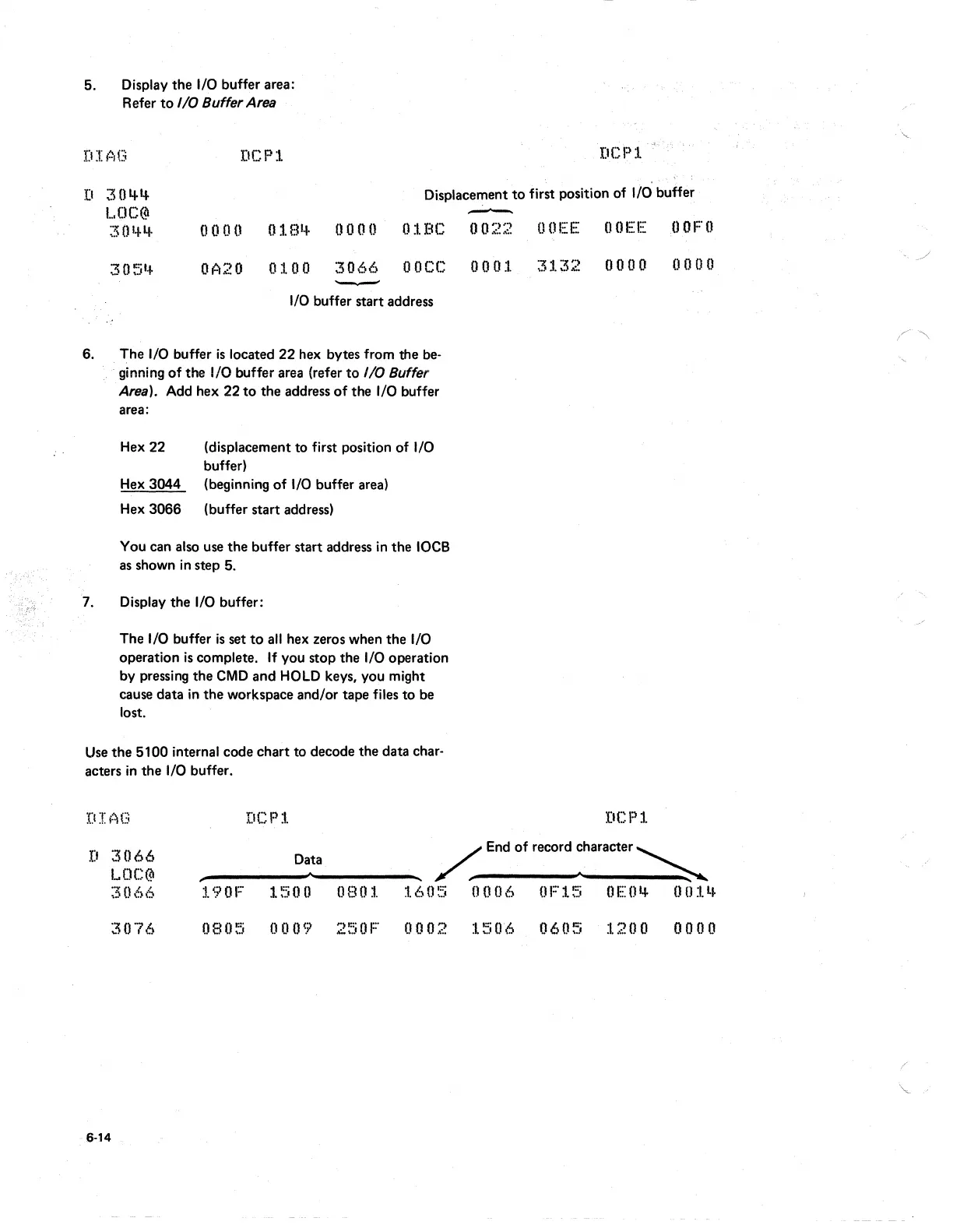
5. Display the I/O buffer area:
Refer
to
I/O
Buffer Area
DCP:L
l:ICPl.
D 30'+'+
LOC@
30'-1-'+
Displacement
to
first position of I/ei buffer
-
0000
018~
0000
01BC
0022
OOEE OOEE
tOFO
305'+
OA20
0100
3066
OOCC
0001
3132
0000 0000
-
I/O
buffer start address
6. . The I/O buffer
is
located
22
hex bytes from the
be-
. ginning
of
the I/O buffer area (refer
to
I/O
Buffer
Area). Add hex 22
to
the address
of
the I/O buffer
area:
Hex
22 (displacement to first position of I/O
buffer)
Hex
3044 (beginning
of
I/O
buffer area)
Hex
3066 (buffer start address)
You can also use the buffer start address
in
the
10CB
as
shown
in
step 5.
7. Display the I/O buffer:
The I/O buffer
is
set
to
a"
hex zeros when the I/O
operation
is
complete.
If
you stop the I/O operation
by pressing the
CMD
and
HOLD
keys, you might
cause data
in
the workspace and/or tape files to be
lost.
Use
the 5100 internal code chart to decode the data char-
acters
in
the
I/O
buffer.
DCPl
DCPl
D
3066
LOC@
;3066
Data
,
"
,-.
____
-""
_____
...
~
End
of
record :haracter
~
190F
l~:iOO
0801
1605
0006
OF15
OEO'+
001'+
3076
080~5
0009
250F
0002
1506
0605
1200
0000
6-14

Table of Contents

Other manuals for IBM 5100

Question and Answer IconNeed help?

Do you have a question about the IBM 5100 and is the answer not in the manual?

IBM 5100 Specifications

General IconGeneral
Release Year1975
RAM16 KB - 64 KB
Storage204 KB tape drive
Display5-inch CRT
Operating SystemAPL/BASIC
ProcessorIBM PALM (1.9 MHz)

Summary

Preface

CE Safety Practices

General Considerations

Safety precautions for working with IBM equipment, general guidelines.

Rescue Breathing for Adults

Step-by-step instructions for administering rescue breathing to adults.

Using the IBM 5100 Portable Computer Maintenance Library

5100 Maintenance Library Overview

Description of the 5100 maintenance library components including MAPs, MIMs, logics, catalogs, and tools.

MAPs

MAP Organization

Flowchart and explanation of how MAPs are structured and used for troubleshooting.

Using the MAPs

Instructions on how to read and follow MAPs, including sequences and probing.

MAP Example

Illustration and explanation of a sample MAP process, including entry/exit points and references.

Maintenance Information Manual

Maintenance

Details on location drawings and procedures for repairing or replacing FRUs.

Diagnostic Aids

Information on diagnostic programs, halt codes, and error conditions.

Theory

Descriptions of functional units and features, including a system overview.

Circuits

Information on card plug charts, signal cable charts, and logic diagrams.

Language Support

Reference material for determining causes of programming problems.

Appendix

Installation procedures and additional maintenance information.

Abbreviations and Glossary

Definitions of terms and abbreviations used in the manual and MAPs.

Index

A detailed listing of all topics within the maintenance information manual.

Related product manuals