Home
IBM
Desktop
Aptiva Series
IBM Aptiva Series Hardware Maintenance
4
of 1
of 1 rating
206 pages
Give review
Manual
Specs
To Next Page
To Next Page
To Previous Page
To Previous Page
Loading...
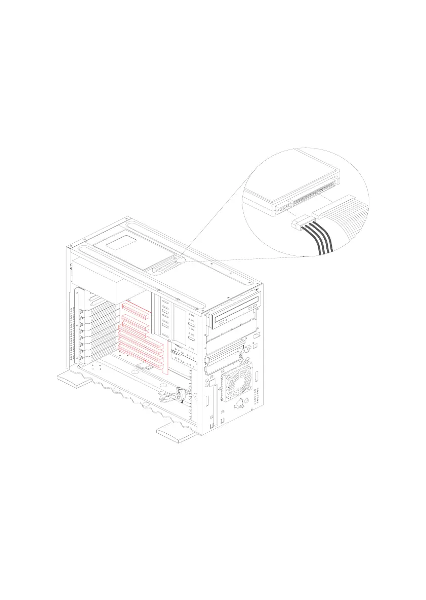
4-16
When installing a drive in bay-6
•
Position a hard disk drive over bay 6 such that the signal and power
connectors face the front panel.
•
Secure the drive with the appropriate screws
•
Connect the drive cables
Figure 4- 13
Reattach The Cables
122
124
Table of Contents
Default Chapter
4
Table of Contents
4
Notices
8
Voltage Supply Switch Settings
8
Safety Information
9
Safety Notices (Multi-Lingual Translations)
10
Laser Compliance Statement
14
Federal Communications Commission (FCC) Notice
15
Federal Communications Commission (FCC) Statement
15
Canadian Department of Communications Compliance Statement
16
Canadian Department of Communications Certification Label
16
Trademarks
17
Preface
18
General Information
20
Chapter Description
21
Diagnostic Information
21
Using the Check Procedures
21
Diagnostic Aids
22
Repair Information
22
Parts/Test Point Locations
23
Safety Inspection Guide
23
Parts Catalog
23
Part Number Index
23
Product Description
24
Hardware Interfaces
28
Memory Map
29
System Input/Output Addresses
30
System Interrupts
31
DMA Channel Assignments
32
Serial Port Addresses
32
Refresh Rates and Monitor Frequencies
33
CMOS Reset
33
Power-On Password
34
Flash (BIOS) Update Procedure
35
Changing the BIOS (Flash ROM) Model Number and Serial Number
36
BIOS Setup Utility
37
Starting the Setup Utility
37
Viewing System Information
39
Changing Disk Drive Configuration
40
Enhanced IDE Features
41
Setting Power Saving Timers
43
Changing Plug and Play Configuration
44
Configuring Startup Options
45
Setting the Date and Time
45
Configuring Advanced Options
46
System Memory
50
Specifications
50
Operating Requirements
52
Special Tools
52
Check Procedures
54
Check Procedures Start
55
Index of Symptoms, Messages, Error Codes, or Beeps
60
Factory-Installed Drive Devices
77
CD-ROM Drive
79
Memory
81
Keyboard
82
Mouse
83
Power Supply
85
Device Presence by Diagnostics Program Test
88
Diagnostics for Factory-Installed Riser Card, or Audio-I/O Card Not Supported by Diagnostics Program
90
Diagnostics for Factory-Installed Fax/Modem Card
95
Monitor
96
Undetermined Problem
98
Diagnostic Aids
100
Introduction
101
Power-On Self Test
101
Diagnostic Diskette
102
Diagnostic Program Features
102
Using the Diagnostic Diskette
103
Creating a Boot Diskette with Drivers
105
To Load the Diagnostics Diskette
106
Repairing Information
109
Removals and Replacements
109
Removal Sequence
110
Identifying the Parts of the System Unit
111
Cover
113
Bays 1, 2, 3 (5.25-In. Internal /External Bays)
114
Bay 4 (3.5-In. FDD Bay)
117
Bay 5 (3.5-In. Internal Bay)
121
Bay 6 (3.5-In. Internal Bay)
122
Power Supply
124
Adapter Cards
125
Riser Card
129
Memory(Simm)
131
Processor Removal
133
RTC Lithium Battery
135
Indicator LED and Cable
136
System Board
138
Handling ESD-Sensitive Parts
140
Software Recovery Procedure
141
Parts/Test Point Loceions
143
System Board Layout
143
System Board Jumper Settings
144
CPU Type Jumper Settings
145
System Board Connect or Functions
146
Power Supply Cable Connector Specifications
148
Audio-I/O Card Layout
150
Audio-I/O Card Connector Functions
150
Factory-Installed Fax/Modem Card Layout
151
Factory-Installed Fax/Modem Card Connector Functions
151
Hard Disk Drive
152
3.5" Hard Disk Drive Jumper Settings
152
5.25" Hard Disk Drive Jumper Settings
153
CD-ROM Drive
154
CD-ROM Drive Connector Features
154
CD-ROM Drive Jumper Settings
154
CD-ROM Emergency-Exit Option <1
155
CD-ROM Emergency-Exit Option <2
155
SIMM Configurations
157
System Board Connector Pin Signals
158
Monitor Port Signals
158
Parallel Port Signals
158
Serial Port Signals
158
Mouse Port Signals
159
Keyboard Port Signals
159
Diskette Cable Connector Signals
160
Hard Disk Cable Connector Signals
161
Safety Inspecion Guide
162
General Guidelines
163
Parts Catalog
164
Assembly 1: System Unit - Exterior
165
Assembly 2: System Unit - Interior
166
Assembly 3: Diskette, CD-ROM Drive
168
Assembly 4: Hard Disk Drives, Audio-I/O Board and Fax / Modem Card
170
Assembly 5: Monitor and Power Cord
174
Assembly 6: Keyboard and Mouse
175
Assembly 7: Software
176
Appendix A. Part Number Index
178
Appendix B. Oneline Support Information
180
Appendix C. Model/Monitor Configurations and FRU Part Numbers
182
Other manuals for IBM Aptiva Series
Quick Start Guide
2 pages
Handbook
164 pages
4
Based on 1 rating
Ask a question
Give review
Questions and Answers:
Need help?
Do you have a question about the IBM Aptiva Series and is the answer not in the manual?
Ask a question
IBM Aptiva Series Specifications
General
Brand
IBM
Model
Aptiva Series
Category
Desktop
Language
English
Related product manuals
IBM Aptiva
2 pages
IBM Aptiva 2170
252 pages
IBM Aptiva 2172
252 pages
IBM Aptiva 2134
266 pages
IBM Aptiva 2158
222 pages
IBM Aptiva 2144
246 pages
IBM 2158240 - Aptiva E - 2158
187 pages
IBM A50
116 pages
IBM NetVista A40
150 pages
IBM A40I TYPE 2271
124 pages
IBM IntelliStation A Pro
106 pages
6269 - NetVista A20 - 64 MB RAM
150 pages
 Loading...


