A.1.2 Floor Stand Overview
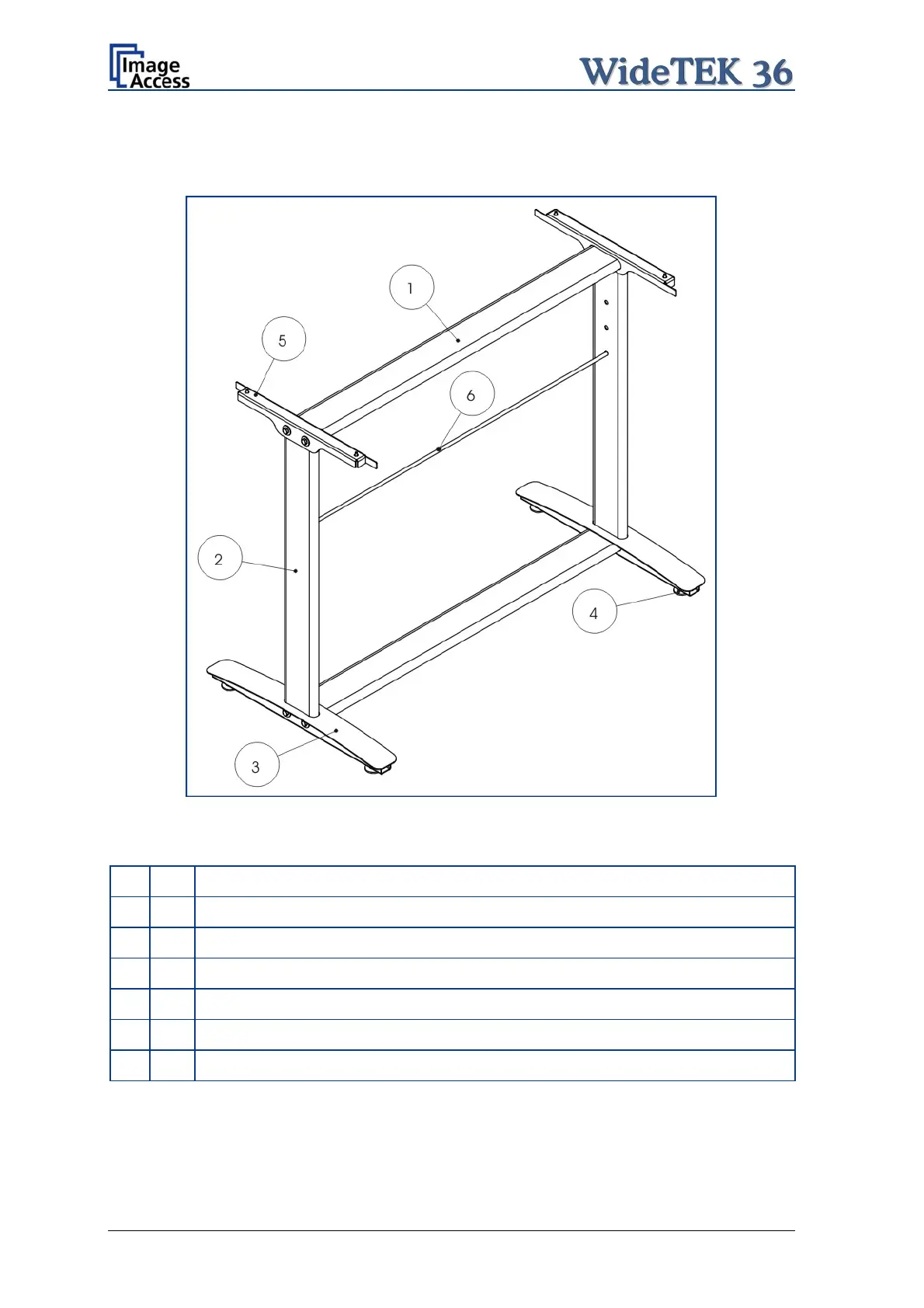
The engineering drawing below shows all major elements of the floor stand.
Picture 4: Technical drawing of floor stand
The floor stand is built out of five different components and one round rod.
No Qty Description
1 2 Horizontal traverse. This part is used on the top as well as on the bottom.
2 2 Vertical leg. This part is used on the left as well as on the right side.
3 2 Foot bracket. This preassembled part is used on the left and right side.
4 4 Adjustable feet. These are preassembled to the foot bracket.
5 2 Top bracket: This part is used on the left and right top side.
6 1 Horizontal rod. This part supports the paper exit basket.
Page 16 Setup and Assembly Manual
 Loading...