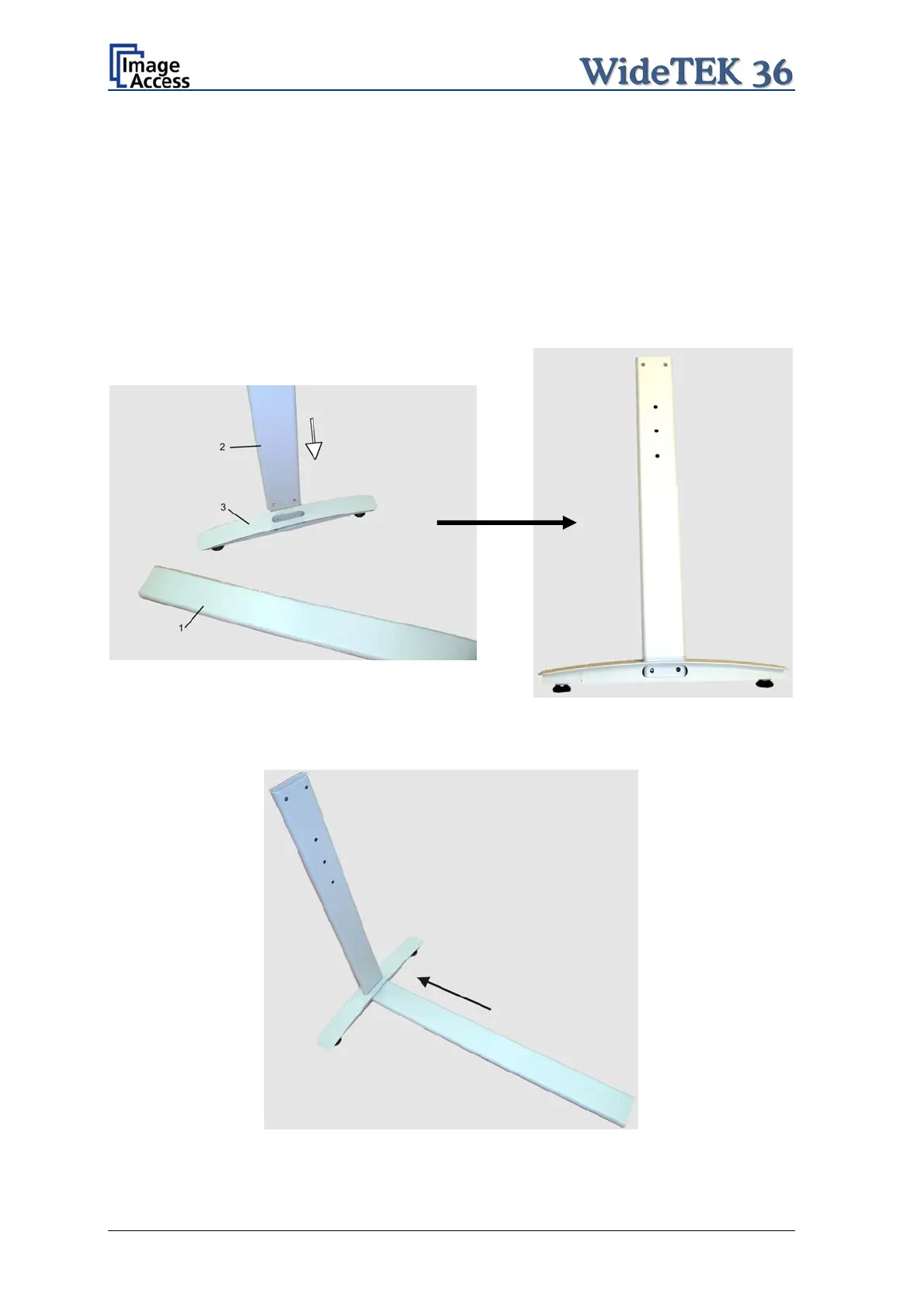
A.2 Assembling the Floor Stand
Start with the foot profile (component #3), the side pillar (component #2), and the traverse
(component #1).
Note: The three boreholes on the vertical leg (part #2) that are only on one side must
face to the inner side of the floor stand. They should also be in the upper part of
the leg. The technical drawing illustrates the correct position.
First insert a vertical leg into a foot bracket. The brackets have a cutout for the traverse.
The foot brackets are designed symmetrically, therefore either one fits left and right.
Picture 6: Side pillar in foot profile
Next, insert the traverse as shown in the picture below.
Picture 7: Traverse inserted into foot bracket
Page 18 Setup and Assembly Manual
 Loading...