MD380 User Manual Desc
ription of Function Codes
- 239 -
Group AC: AI/AO Correction
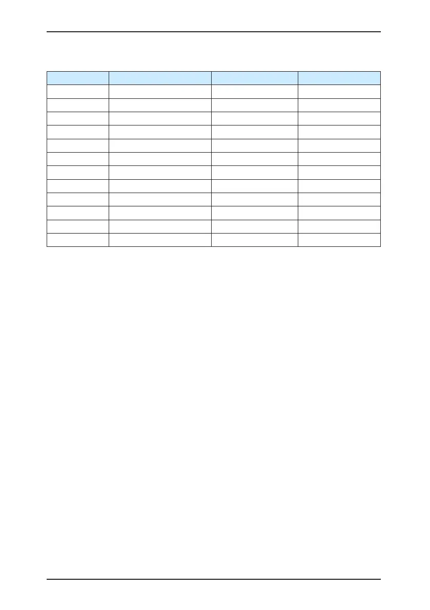
Function Code Parameter Name Setting Range Default
AC-00 AI1 measured voltage 1 0.500–4.000 V Factory-corrected
AC-01 AI1 displayed voltage 1 0.500–4.000 V Factory-corrected
AC-02 AI1 measured voltage 2 6.000–9.999 V Factory-corrected
AC-03 AI1 displayed voltage 2 6.000–9.999 V Factory-corrected
AC-04 AI2 measured voltage 1 0.500–4.000 V Factory-corrected
AC-05 AI2 displayed voltage 1 0.500–4.000 V Factory-corrected
AC-06 AI2 measured voltage 2 6.000–9.999 V Factory-corrected
AC-07 AI2 displayed voltage 2 9.999–10.000 V Factory-corrected
AC-08 AI3 measured voltage 1 9.999–10.000 V Factory-corrected
AC-09 AI3 displayed voltage 1 9.999–10.000 V Factory-corrected
AC-10 AI3 measured voltage 2 9.999–10.000 V Factory-corrected
AC-11 AI3 displayed voltage 2 9.999–10.000 V Factory-corrected
These parameters are used to correct the AI to eliminate the impact of AI zero offset and
gain.
They have been corrected upon delivery. When you resume the factory values, these
parameters will be restored to the factory-corrected values. Generally, you need not perform
correction in the applications.
Measured voltage indicates the actual output voltage value measured by instruments such
as the multimeter. Displayed voltage indicates the voltage display value sampled by the AC
drive. For details, refer to U0-21, U0-22 and U0-23.
During correction, send two voltage values to each AI terminal, and save the measured
values and displayed values to the function codes AC-00 to AC-11. Then the AC drive will
automatically perform AI zero offset and gain correction.
If the input voltage and the actual voltage sampled by the AC drive are inconsistent, perform
correction on site. Take AI1 as an example. The on-site correction is as follows:
1) Send a voltage signal (approximately 2 V) to AI1.
2) Measure the AI1 voltage and save it to AC-00.
3) View the displayed value of U0-21 and save the value to AC-01.
4) Send a voltage signal (approximately 8 V) to AI1.
5) Measure AI1 voltage and save it to AC-02.
6) View the displayed value of U0-21 and save the value to AC-03.
At correction of AI2 and AI3, the actually sampled voltage is respectively queried in U0-22
and U0-23.
For AI1 and AI2, 2 V and 8 V are suggested as the correction voltages. For AI3, -8 V and 8
V are suggested.

 Loading...