Operation, Display and Application Examples
MD380 User Manual
- 60 -
■
Parameter Setting and Operation of JOG Running in DI Terminal Control
For equipment that requires frequent JOG operations, such as textile machine, it
is more convenient to control JOG running by using keys or buttons. To achieve
convenient control, perform the setting according to the following gure.
Figure 4-16 JOG running in DI terminal control
F4-00
F4-01
F4-02
F4-03
F4-04
.
.
.
.
4
5
.
F0-02 = 1
JOG control
button
Terminal
Function
value
Setting
value
DI1
DI2
DI3
DI4
DI5
.
COM
Forward
JOG
Terminal
control
Parameter setting
Forward
JOG
Reverse
JOG
FJOG
RJOG
Reverse
JOG
F8-00 (JOG running frequency)
F8-01 (JOG acceleration time)
F8-02 (JOG deceleration time)
Forward
JOG
Reverse
JOG
(Stop state)
F8-13 = 1
After performing the setting according to the preceding gure, press the FJOG button
in stop state of the AC drive. Then, the AC drive starts forward JOG. After you press the
FJOG button again, the AC drive decelerates to stop.
4.8 Setting the Running Frequency
The AC drive provides two frequency sources, namely, main frequency source X and
auxiliary frequency source Y. You can select one frequency source and switch over between
the two sources. You can also perform superposition on the two sources by setting the
calculation formula to meet different control requirements of different scenarios.
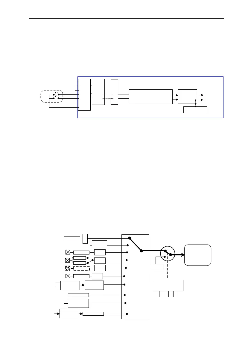
4.8.1 Frequency Setting by the Main Frequency Source
There are nine setting modes of main frequency sources, digital setting (UP/DOWN
modification, non-retentive at power failure), digital setting (UP/DOWN modification,
retentive at power failure), AI1, AI2, AI3, pulse setting, multi-reference, simple PLC, and
communication setting. You can select one in F0-03.
Figure 4-17 Frequency set by the main frequency source
F0-03 (Main
frequency
source X
selection)
0
0-10 V
1
▲
▼
Retentive at
power failure
4-20 mA
J8
F0-08
AI1
AI2
AI
3
On extension
board
F4-04 = 30
DI5
Pulse
setting
2
3
4
5
F4-00 to F4-04
= 12/13/14/15
Multi-speed
6
Analog
Analog
DI1 to DI10
FC-00 to FC-15
(each
frequency)
Group FC
Simple PLC
Group FA
PID
H1000 register
Communication
setting
Host
computer
7
8
9
AI1 to AI2
F4-33
F4-29 to
F4-32
Analog
FD-00 to FD-05
Communication
configuration
DI5 (f)
Digital
setting
Main
frequency
source X
F4-00 to
F4-09 = 39
DI1 to DI10
Frequency
switchover
F0-08
0-10 V
-10 V to 10 V
F4-33
F4-33

 Loading...