Operation, Display and Application Examples
MD380 User Manual
- 72 -
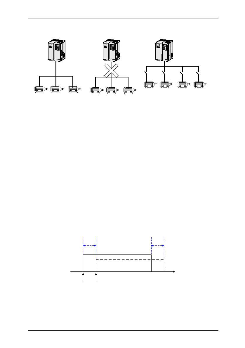
Figure 4-30 Driving multiple motors
F0-01 = 2 F0-01 = 0 or
1 F0-01 = 0 or 1
F0-24
= 0
F0-24
= 1
F0-24
= 2
F0-24
= 3
Motor 1 Motor 2 Motor 3 Motor 4
In the vector control mode, up to 4 motors
can be driven at different time. The motor
parameters are restored respectively.
In the vector control mode,
multiple motors cannot be
driven simultaneously.
In the V/F control mode,
multiple motors can be
driven simultaneously.
4.10 Use of DI Terminals
The control board provides ve DI terminals DI1 to DI5. You can obtain another DI terminals
DI6 to DI10 by installing an I/O extension card.
The internal hardware of DI terminals are configured with 24 VDC power supply for
detection. You can input a signal to a DI terminal of the AC drive only by shorting the DI
terminal and COM.
By default, F4-38 = 0000 and F4-39 = 0000. When a DI terminal is shorted to COM, it is
active (logic 1). When a DI terminal is not shorted to COM, it is inactive (logic 0).
You can change the DI terminal active mode. That is, a DI terminal is inactive (logic 0) when
being shorted with COM, and active (logic 1) when being not shorted to COM. In this case,
it is necessary to change the corresponding bit in F4-38 and F4-39 (these two parameters
respectively specifying the active mode setting of DI1 to DI5 and DI16 to DI10) to 1.
The AC drive also provides F4-10 (DI filter time) for the DI signal to improve the anti-
interference level. For DI1 to DI3, the AC drive provides the DI signal delay function,
convenient for some applications requiring delay.
Figure 4-31 DI delay setting
t
DI hardware
signal
Internal DI
signal
T T
DI1 delay set in F4-35
DI2 delay set in F4-36
DI3 delay set in F4-37
The preceding 10 DI terminals can be dened in function codes F4-00 to F4-09. Each DI can be
allocated with their respective function from the 50 functions. For details, see descriptions of F4-
00 to F4-09.
The hardware design allows only DI5 to receive high-speed pulse signal. If high-speed pulse
count is required, use DI5.