Operation, Display and Application Examples
MD380 User Manual
- 74 -
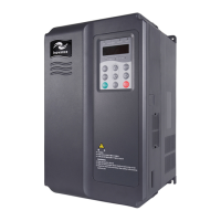
Figure 4-32 Dening corresponding relationship of the voltage or current and actual setting
or feedback
Vi
D %
Vi
D
%
Vi
D %
U0
-09
U0-10
U0-11
Unit's digit: AI1
Curve selection: 1
−
5
Ten's digit: AI2
Curve selection: 1
−
5
Hundred's digit: AI3
Curve selection: 1
−
5
F4-33: AI curve selection
AI1
AI3
AI2
AI terminal Sampling
%
%
%
AI1 internal
calculation value
AI2 internal
calculation value
AI3 internal
calculation value
The user can preset up
to 5 curves. Different
AIs can use one curve.
Curve 1: F4-13 to
F4-17
Curve 2: F4-18 to
F4-22
Curve 5
: A6-08 to
A6-15
J8
V
I
V
V
The sampling of AI terminals can be queried in U0-09 to U0-11. The calculation value is for
internal subsequent calculation and cannot be directly read by the user.
4.13 Use of AO Terminals
The AC drive supports a total of two AO terminals, among which AO1 is provided by the
control board and AO2 is provided on the extension card.
Terminal Output Signal Characteristic
AO1-GND
If J5 is connected to the position with "V" mark, it outputs the signal of 0–10 VDC.
If J5 is connected to the position with "I" mark, it outputs the signal of 0–20 mA.
AO2-GND It is provided on the extension card and outputs the signal of 0–10 VDC.
AO1 and AO2 can be used to indicate the internal running parameters in the analog mode.
The property of indicated parameters can be dened by F5-07 and F5-08.
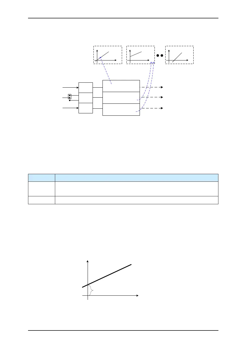
The designated running parameters can be rectied before output. The rectication feature
is Y = kX + b, among which "X" indicates the running parameters to be output, and "k" and
"b" of AO1 can be set by F5-10 and F5-11.
Figure 4-33 Setting of "k" and "b" of AO1
b = F5-10
K = F5-11
Parameter to be output
AO1 output
(Y after rectification)
(X before rectification)

 Loading...