16
LBK System| Instruction manual v1.3 SEP 2019 |LBK-System_instructions_en v1.3|© 2018-2019 Inxpect SpA
l machinery emergency button (low logic level (0) = stopping enabled)
l button for enabling machinery restart (high logic level (1) for 200 ms and transition to low logic level (0)
= restart enabled)
The inputs are type1, type 2 and type 3 (see "Voltage and current limits for digital inputs" on page62).
The function of the inputs can be configured through the Inxpect Safety application.
3.2.10 SNS input
The controller also has an SNS input (high logic level (1) = 24 V) to check the correct functioning of the chip
that detects the status of the inputs.
NOTICE: if at least one input is connected, the SNS input must also be connected.
3.3 Sensors LBK-S01
3.3.1 Functions
The sensors perform the following functions:
l Detect motion in their field of vision.
l Send the motion detection signal to the controller through CAN bus.
l Signal failures detected in diagnostics on the controller through CAN bus.
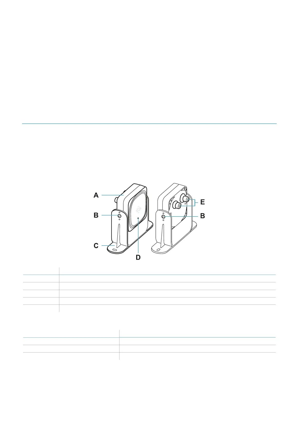
3.3.2 Structure
Part Description
A Sensor
B Screws for fastening the sensor at a specific inclination
C Perforated bracket for installing the sensor on the ground or on the machinery
D Status LED
E Connectors for connecting the sensors in a chain and to the controller
3.3.3 Status LED
Status Meaning
Steady on Normal functioning and no detected motion
Rapid flashing on (100 ms) Normal functioning and motion detected
Other conditions Error. See "Sensor LED" on page53
3. Get to know LBK System

 Loading...
