28
LBK System| Instruction manual v1.3 SEP 2019 |LBK-System_instructions_en v1.3|© 2018-2019 Inxpect SpA
Example 2
l Machinery stopping time =0.2 s
l Sensor installation height (H) = 800 mm.
l Sensor installation inclination (I) = -20°
T = 0.1 s + 0.2 s = 0.3 s
C
h
= 1200 - 0.4 * 800 = 880 mm
C
α
= (-(-20))* 16 = 320 mm
S =1600 * 0.3 + 880 + 320 = 1680 mm
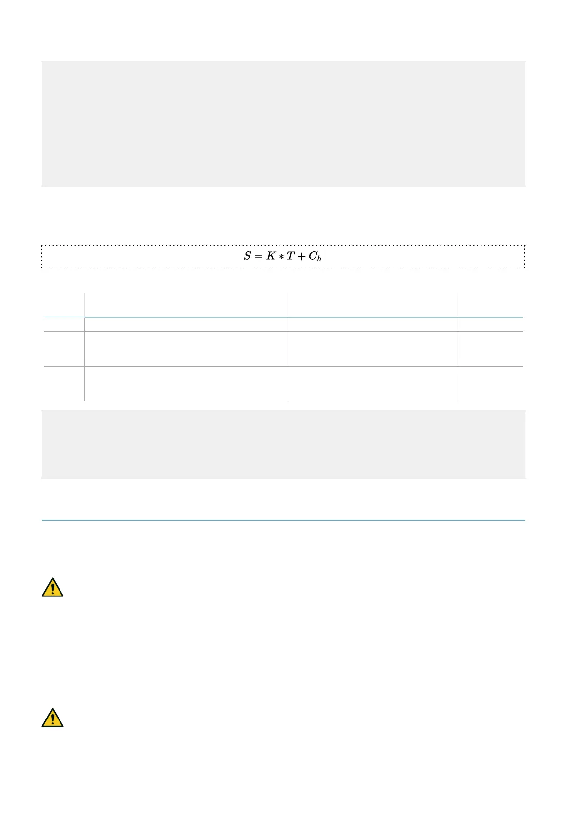
5.3.3 Sensor height > 1 m
To calculate the depth of the dangerous area (S) for sensors with installation heights greater than 1 m, use
the following formula:
Where:
Variable Description Value
Measurement
unit
K Maximum dangerous area access speed 1600 mm/s
T Total system stopping time (LBK System +
machinery)
0.1 + Machinery stopping time
(calculated in accordance with ISO
13855:2010 standard)
s
C
h
Constant that takes into account the sensor
installation height (h) according to standard
ISO 13855:2010
850 mm
Example 1
l Machinery stopping time =0.5 s
T = 0.1 s + 0.5 s = 0.6 s
S =1600 * 0.6 + 850 = 1810 mm
5.4 Calculation of position for sensor height < 1 m
5.4.1 Introduction
The formulas for calculating the optimum position of the sensor for sensors with installation heights less
than 1 m are reported as follows.
WARNING! Define the optimum sensor position based on the risk assessment requirements.
5.4.2 Overview of possible installation-inclination configurations
The configurations with possible heights (h) and inclinations (α) are presented as follows:
l 1 = Configuration 1 with sensor facing up (α positive, field of vision not intersecting the ground)
l 2 = Configuration 2 with straight sensor (α = 0, field of vision intersecting the ground at one point only)
l 3 = Configuration 3 with sensor facing down (α negative, field of vision intersecting the ground at two
points)
l X = Configuration not possible
WARNING! With configurations not listed in these tables or marked with an “x”, safety functions
are not guaranteed.
5. Sensor position
 Loading...
