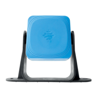
9.1.3 Sensor features
Connectors 2 5-pin M12 connectors (1 male
and 1 female)
CAN bus
termination
resistance
120 Ω (not supplied, to be
installed with termination
connector)
Power supply 12 V dc ± 20%, through controller
Consumption Max 1.2 W
Degree of
protection
IP67
Material Sensor:PA66
Bracket: PA66 and glass fiber
(GF)
9.1.4 CAN bus cables
specifications
Section 2 x 0.25 mm
2
power supply
(recommended: 2 x 0.34 mm
2
)
2 x 0.25 mm
2
data line
(recommended: 2 x 0.34 mm
2
)
Type Two for power supply and two for
data line (recommended: two
pairs of twisted pairs, power
supply and data line)
Connectors 5-pole M12, see "Connectors M12
CAN bus" on the next page
Impedance 120 Ω ±12 Ω (f = 1 MHz)
Shield Shield with twisted wires in tin-
plated copper. To be connected
to earth circuit on the power
supply terminal block of the
controller.
Length 30 m from controller to sensor
(configuration with one sensor)
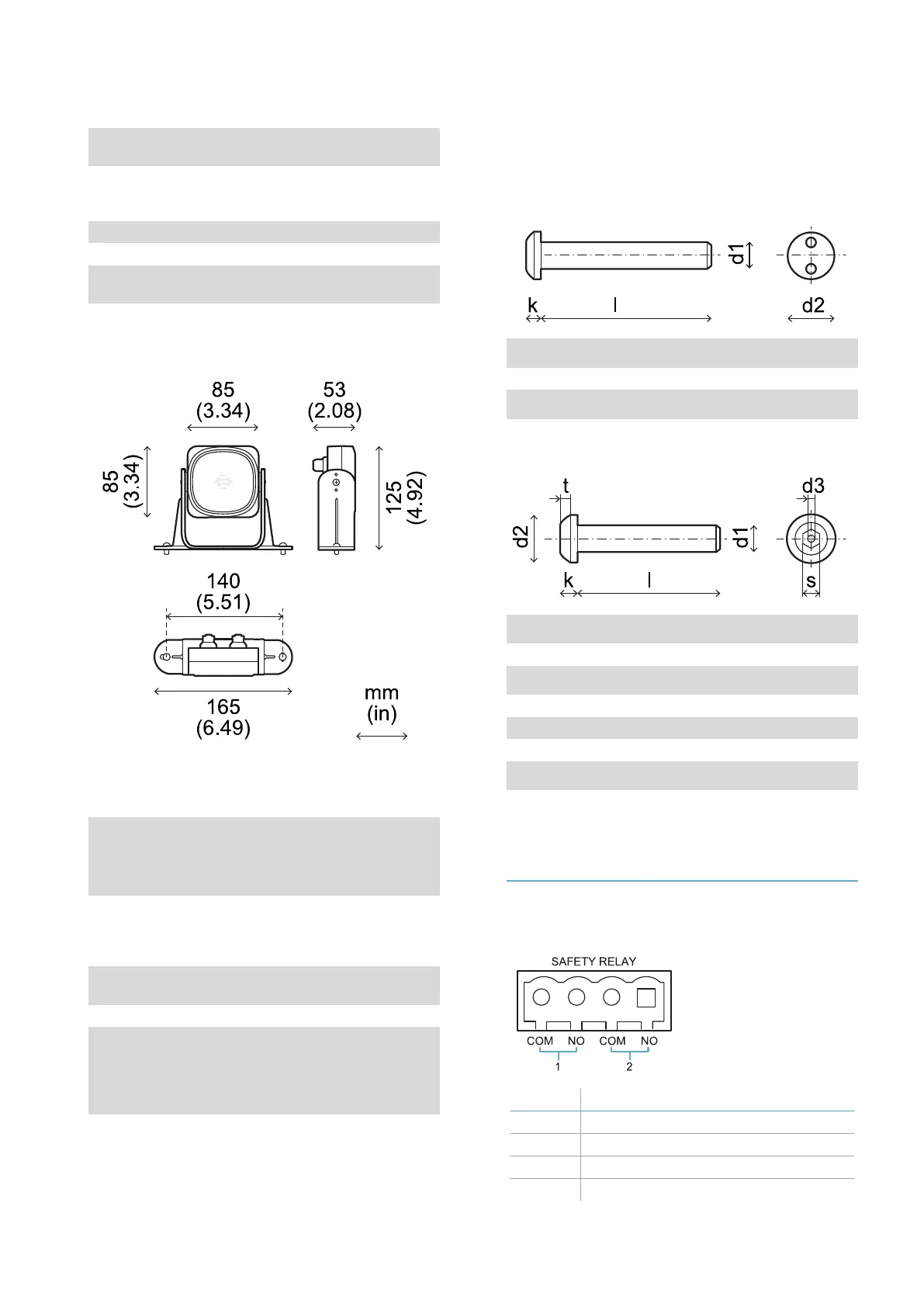
9.1.5 Side screws specifications
The side screws can be:
l cheese head and two hole drive
l button head
Cheese head and two hole drive screws
d
1
M4
l 10 mm
d
2
7.6 mm
k 2.2 mm
Button head screws
d
1
M4
l 10 mm
d
2
7.6 mm
k 2.2 mm
t min 1.3 mm
s 2.5 mm
d
3
max 1.1 mm
9.2 Terminal blocks and
connectors pin-outs
9.2.1 Safety outputs terminal
block
Terminal Description
COM Common safety output 1
NO Relay output normally open
COM Common safety output 2
NO Relay output normally open
9. Technical references
LBK System| Instruction manual v1.3 SEP 2019 |LBK-System_instructions_en v1.3|© 2018-2019 Inxpect SpA
61
 Loading...
