Basic Operation
Pins Introduction
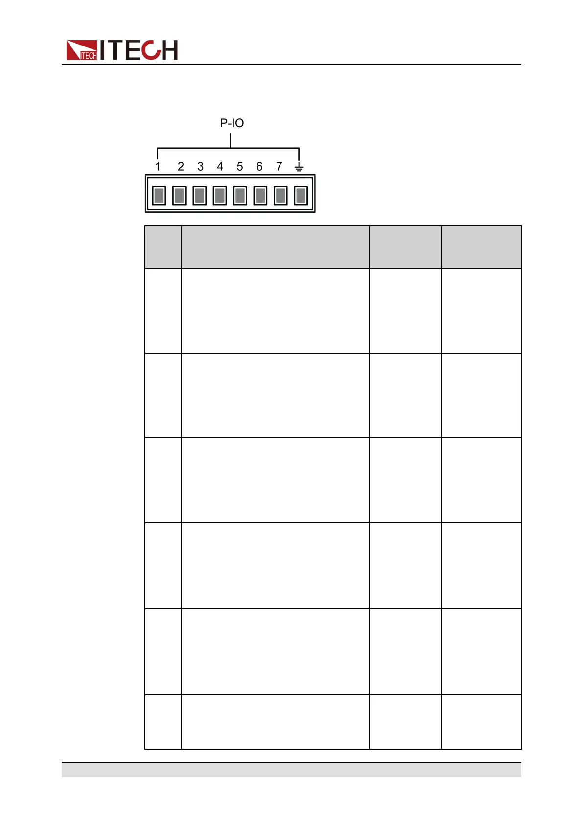
The appearance of the terminals are shown below.
Pin Description Properties
(Default
function)
Properties
(General I/O
function)
1 Corresponds to the function set in the
System→Digital Port→IO–1. Ps-
Clear, Not-Invert menu item. For pa-
rameter introduction, see 5.11.1 IO–
1. Ps-Clear, Not-Invert.
Pulse signal Level or PWM
signal
2 Corresponds to the function set in the
System→Digital Port→IO–2. Ps,
Not-Invert menu item. For parameter
introduction, see 5.11.2 IO–2. Ps,
Not-Invert.
Level signal Level or PWM
signal
3 Corresponds to the function set in the
System→Digital Port→IO–3. Off-
Status, Not-Invert menu item. For
parameter introduction, see 5.11.3
IO–3. Off-Status, Not-Invert.
Level signal Level or PWM
signal
4 Corresponds to the function set in the
System→Digital Port→IO–4. Ext-
Trig, Not-Invert menu item. For pa-
rameter introduction, see 5.11.4 IO–
4. Ext-Trig, Not-Invert.
Pulse signal Level or PWM
signal
5 Corresponds to the function set in the
System→Digital Port→IO–5. INH-
Living, Not-Invert menu item. For
parameter introduction, see 5.11.5
IO–5. INH-Living, Not-Invert.
Pulse signal Level or PWM
signal
6 Corresponds to the function set in the
System→Digital Port→IO–6. Sync-
On, Not-Invert menu item. For
Pulse signal Level or PWM
signal
Copyright © Itech Electronic Co., Ltd.
79

 Loading...


