Basic Operation
Pin Description Properties
(Default
function)
Properties
(General I/O
function)
parameter introduction, see 5.11.6
IO–6. Sync-On, Not-Invert.
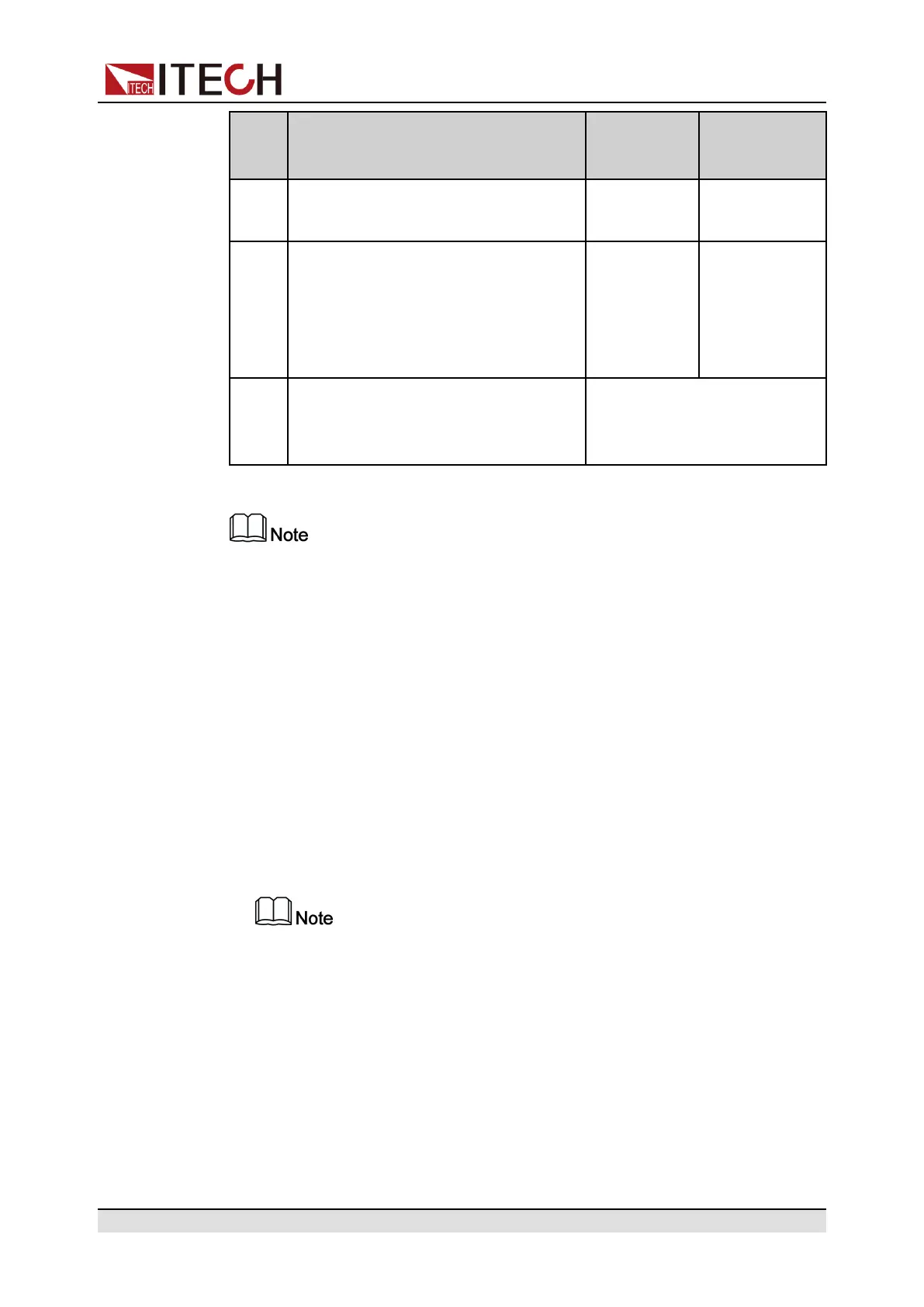
7 Corresponds to the function set in the
System→Digital Port→IO–7. Sync-
Off, Not-Invert menu item. For pa-
rameter introduction, see 5.11.7 IO–
7. Sync-Off, Not-Invert.
Pulse signal Level or PWM
signal
GND Ground terminal, that is, the negative
terminal corresponding to each of the
above 7 pins.
Level signal
In this chapter, all the pulse signals involved in the digital I/O function are
switched from high level to low level.
Taking pin 1 as an example, IO–1. Ps-Clear, Not-Invert contains three function
options, the first option Ps-Clear is the default function, and this function is also
a special custom function unique to this pin (the seven pins each have a differ-
ent custom function). The second and third options (Input and Output) are the
general digital I/O function, and the parameter settings and functions of the sev-
en pins are the same.
General Digital I/O Function
• Under the default condition (Not-Invert), when the pin (1 to 7) is configured
as Output, it can output the high level (False) or low level (True).
If the corresponding pin is configured as Invert, it means that the digital
signal is inverted and will output low level or high level.
• Under the default condition (Not-Invert), when the pin (1 to 7) is configured
as Output→PWM, the user needs to set the frequency (PWM Freq) and du-
ty cycle (PWM Duty) values. For example, if the PWM Freq is set to 100Hz
and the PWM Duty is set to 10%, the output waveform is as follows:
Copyright © Itech Electronic Co., Ltd.
80