ELECTRICAL
4222983 Second Edition 4-39
4
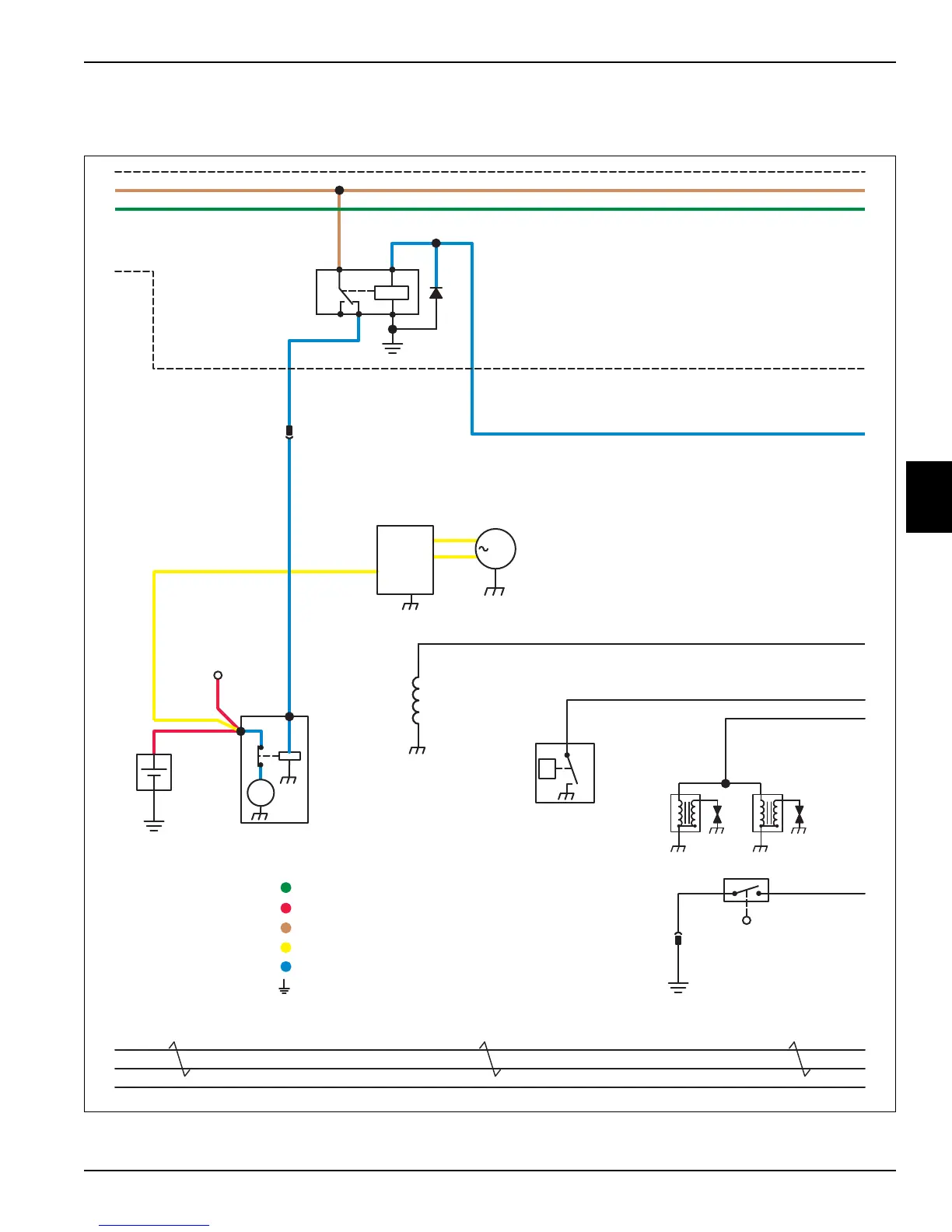
Gasoline Engine Circuit Schematic
Continued
Figure 4-25
312 Brn
P
B1
Engine
Oil
Pressure
Switch
273 Red
G1
12V
Battery
+
-
To
PDU
Stud 6
6A Red
M1
Starter
Motor
M
274
Wht
274
Wht
6
Red
48V Switched Power 48V Switched Power
12V Switched Power 12V Switched Power
CAN Shield
CAN Low
CAN High
CAN Shield
CAN Low
CAN High
CAN Shield
CAN Low
CAN High
CAN Shield
CAN Low
CAN High
13 Wht/Red13 Wht/Red
J1-9 J1-6
J26-2
15
Wht/
Yel
K4
Start
Relay
8787A 85
8630
V4
A1
Power
Distribution
Unit
(PDU)
273
Red
Y2
Fuel
Shutoff
Solenoid
E2
Ignition
Module
E3
Ignition
Module
276 Vio
J32-1
J32-2
J59-Output
G
G3
Stator
N1
Voltage
Regulator
Wht
1E
Blk
Blk
J61-2 J61-1
J97-2
B3
Fuel
Level
Switch
GC2
Start Circuit
Charging Circuit
48V Unswitched Power Circuit
12V Switched Power Circuit
Ground Circuit
48V Switched Power Circuit
TN1669

 Loading...