4-152 4222983 Second Edition
ELECTRICAL
4
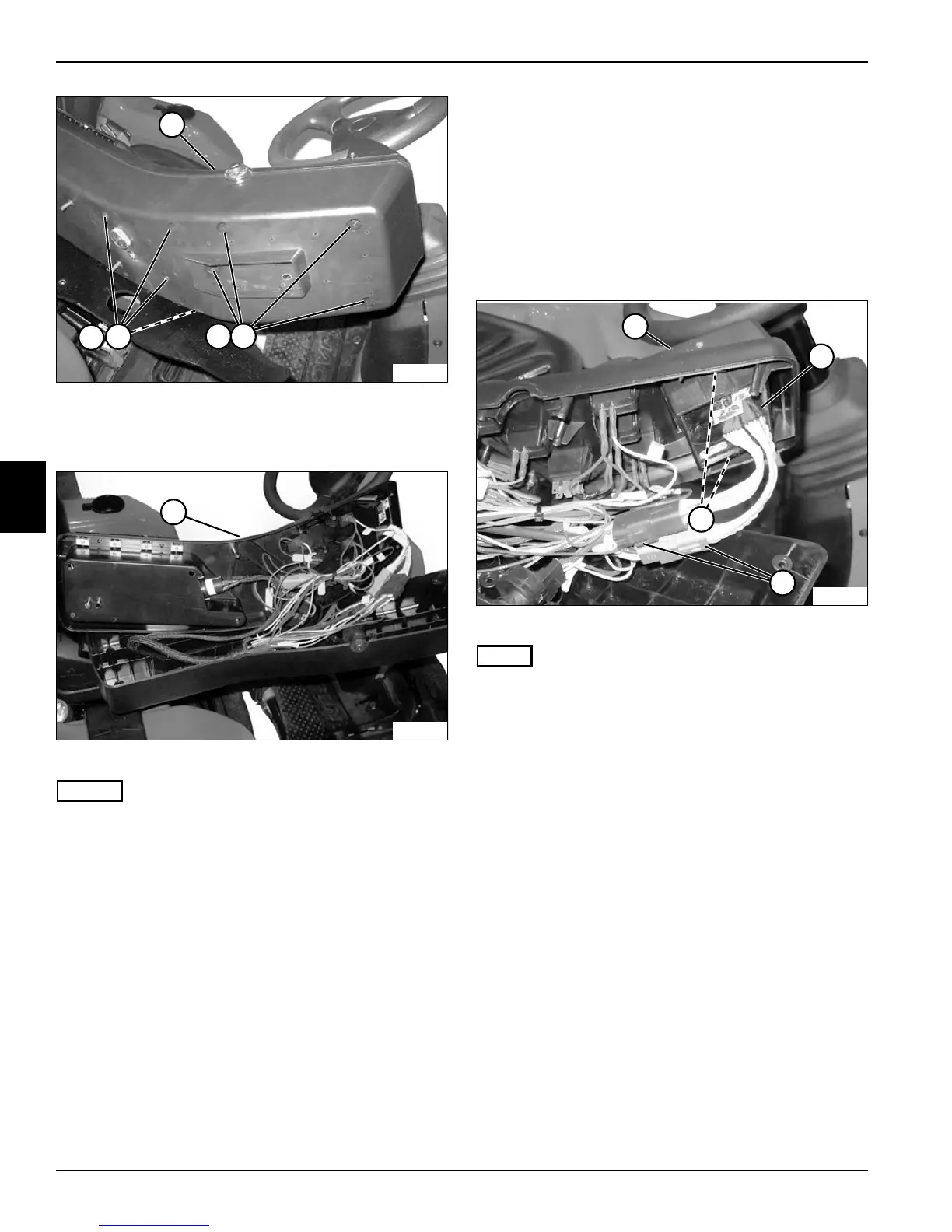
Figure 4-129
4. Remove eight screws (5) and washers (6) from the
underside of instrument panel (7).
Figure 4-130
NOTES
• Label all wires before disconnecting to ensure correct
installation.
• If moving the instrument panel aside, use caution to
prevent stretching or pinching the wires.
5. Lift and move the instrument panel (7) aside or
service components as needed.
Installation Notes
• Anti-seize must be applied to screw threads when
installing instrument panel.
• Apply dielectric grease (Jacobsen PN 365422) to any
connectors removed.
• Use new cable ties to secure wire connectors and
wire harness.
• Install the instrument panel by reversing the order of
removal.
LCD
Removal and Installation
See Figure 4-131.
1. Park the mower safely. (See “Park Mower Safely” on
page 1-6.)
2. Remove instrument panel. (See “Instrument Panel”
on page 4-151.)
Figure 4-131
NOTE
Label all wires before disconnecting to ensure correct
installation.
3. Disconnect LCD wire connectors (1).
4. Squeeze the two clips (2) securing the LCD.
5. Remove LCD (4) from the top section of the
instrument panel (3).
Installation Notes
• Apply dielectric grease (Jacobsen PN 365422) to
connections.
• Install LCD by reversing the order of removal.
TN2332
5
5
6
7
6
7
TN2336
TN2333
1
3
4
2

 Loading...