23 - 2
Loader Valve - Pressure Testing
Unloader Valve
Make sure that the hydraulic oil is at working temperature,
i.e. 50°C (122°F).
Lower the backhoe bucket and loader shovel to rest on the
ground; stop the engine; operate the control levers to vent
residual hydraulic pressure.
Make sure that the ‘hydraulic speed control’ and ‘smooth
ride system’ facilities are NOT switched on, otherwise the
correct unloader valve pressure cannot be obtained.
If the machine has a front-mounted roadbreaker, ensure that
the roadbreaker control valve lever is in the 'off' position
(lever down), otherwise the roadbreaker relief valve will
operate and prevent unloader valve pressure from being
reached.
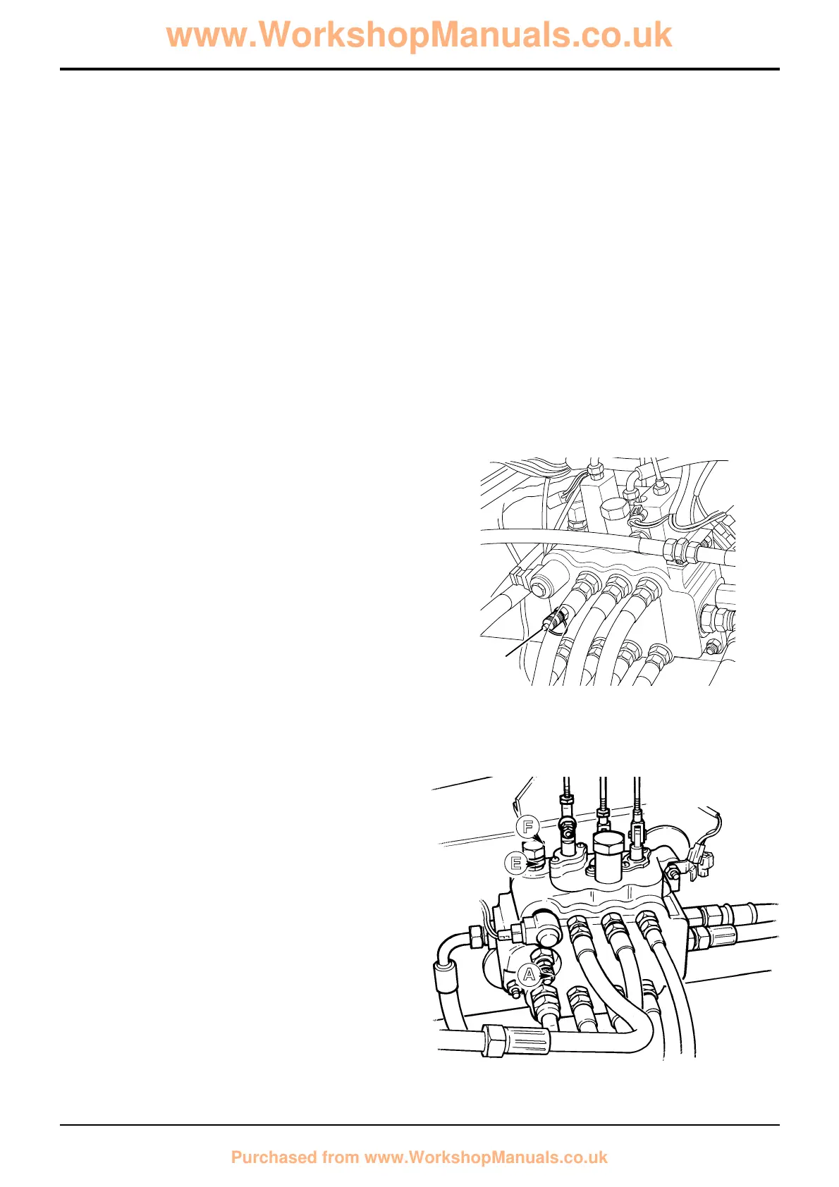
1 Connect a 0 - 400 bar (0 - 6000 lbf/in
2
) pressure gauge
to pressure test connector A.
2 With the engine running at 1500 revs/min, slowly
operate arms raise or lower.
Note 1: The arms raise or lower service is specified because
it has no auxiliary relief valve (A.R.V.). Selecting this service
ensures that the pressure vents through the M.R.V. and not
an A.R.V.
3 When the service reaches full travel, return the lever to
the neutral position. Select the service again, very
slowly, the pressure gauge will rise until a step/kick is
seen in the rate of change in the pressure increase. This
is the start of unloader operation. Keep selecting the
service until a sudden sharp increase in pressure is
observed with a change of engine sound, this point is
the unloader setting and should be as specified in
Technical Data.
4 If the pressure is incorrect, slacken locknut E and
adjust cap F. Turn it clockwise to increase pressure and
anti-clockwise to decrease the pressure. When the
pressure is correct, tighten the locknut and check the
pressure again. Adjust as required.
If the correct pressure cannot be achieved, add or
subtract shims as required, refer to Loader Valve -
Fixed Flow, Dismantling and Assembly - Unloader
Valve.
Section E
Hydraulics
9803/3280
Section E
23 - 2
Issue 1
Service Procedures
S266300
E
F
A
 Loading...