94 - 3
Drive Head-Assembly
Pinion Depth
Determine the pinion depth setting as follows:
Note: See page Crownwheel and Pinion for general
guidance on crownwheel and pinion adjustment.
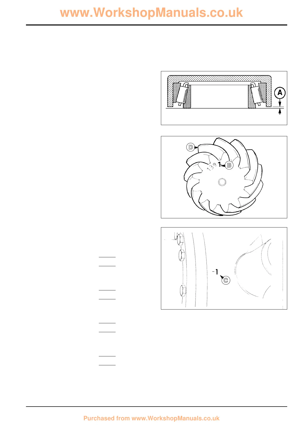
1 Assemble the pinion inner bearing and its cup on a flat
surface.
2 Place Service Tool 892/00174 over the bearing assembly.
Measure gap A. Add tool depth (30.01 mm) to gap A to
give bearing depth.
3 Note the mounting distance figure B etched on the pinion
and the deviation figure C on the drive head housing.
Both figures are in units of 0.01 mm.
Note: The pinion depth may be etched on the gear face B or
on the rear of a gear tooth D.
4 If dimension B is positive, add it to the bearing depth. If
dimension B is negative, subtract it from the bearing
depth.
5 If dimension C is positive, subtract it from the total. If
dimension C is negative, add it to the total.
6 Subtract the result from the standard value of 31.19 mm
to give the required shim thickness.
Example (Dimensions in mm)
Dimension A 0.25
Add tool depth + 30.01
Total 30.26
Add dimension B if positive.
(Subtract if negative.) + 0.01
Total 30.27
Add dimension C if negative.
(Subtract if positive.) + 0.01
Total 30.28
Standard Value 31.19
Less calculated total from above - 30.28
SHIM THICKNESS 0.91
Section F Transmission
9803/3280
Section F
94 - 3
Issue 1
Rear Axle - SD80, PD70
S256110
S256120
B
C
S184400
D

 Loading...