50 - 6
Dismantling and Assembly (cont’d)
Assembly
Before assembly make sure all parts are clean and
serviceable.
1 Fit a new shaft seal 14 if removed. Install the seal as
shown. Press the seal into the housing using a suitable
spacer block and bench press.
2 Coat the the shaft and ball pockets of rotor 9 and the
ball pockets of housing 15 with silicone grease.
3 Insert the three ball bearings 11 into the pockets in the
housing 15. Insert ball spacer 10.
4 Slide rotor 9 through the casting and seat the ball
pockets against the bearings.
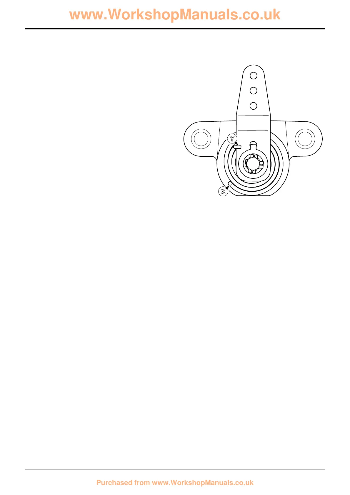
5 Position spring 8 over the shaft of rotor 9. Insert the
large diameter end of the spring into hole X in the face
of the housing.
6 Locate the small diameter end of spring 8 around the
outside edge of lever 7 as shown at Y.
7 Fit lever 7. Align the lever to the mark made during
dismantling.
8 Hold the lever against the tension of the spring and fit
washers 6 and 5, and new anti-rotation clip 4. Fit bolt 3
and tighten to 13-16 Nm (9-12 lbf ft).
9 Bend up a tab of the anti-rotation clip that aligns with
one of the flats on the bolt.
10 Fit the new brake pads, refer to Service Procedures -
Parking Brake - Renewing the Brake Pads.
11 Lubricate the O-rings 13 and bushes 12 with silicone
grease. Fit O-rings into the housing and insert mounting
bushes. Wipe off any excess grease.
12 Before fitting the calliper, ensure the lever rotates
smoothly and that the lever side pad 2 returns to the off
position when the lever is released.
13 Refit the brake calliper. Refer to Calliper - Removal
and Replacement.
14 Adjust the parking brake, refer to Service Procedures
- Parking Brake - Adjustment.
Torque Settings
Item Nm lbf ft
3 13-16 9-12
Section G Brakes
9803/3280
Section G
50 - 6
Issue 1
Parking Brake
A348331
Y
X
 Loading...