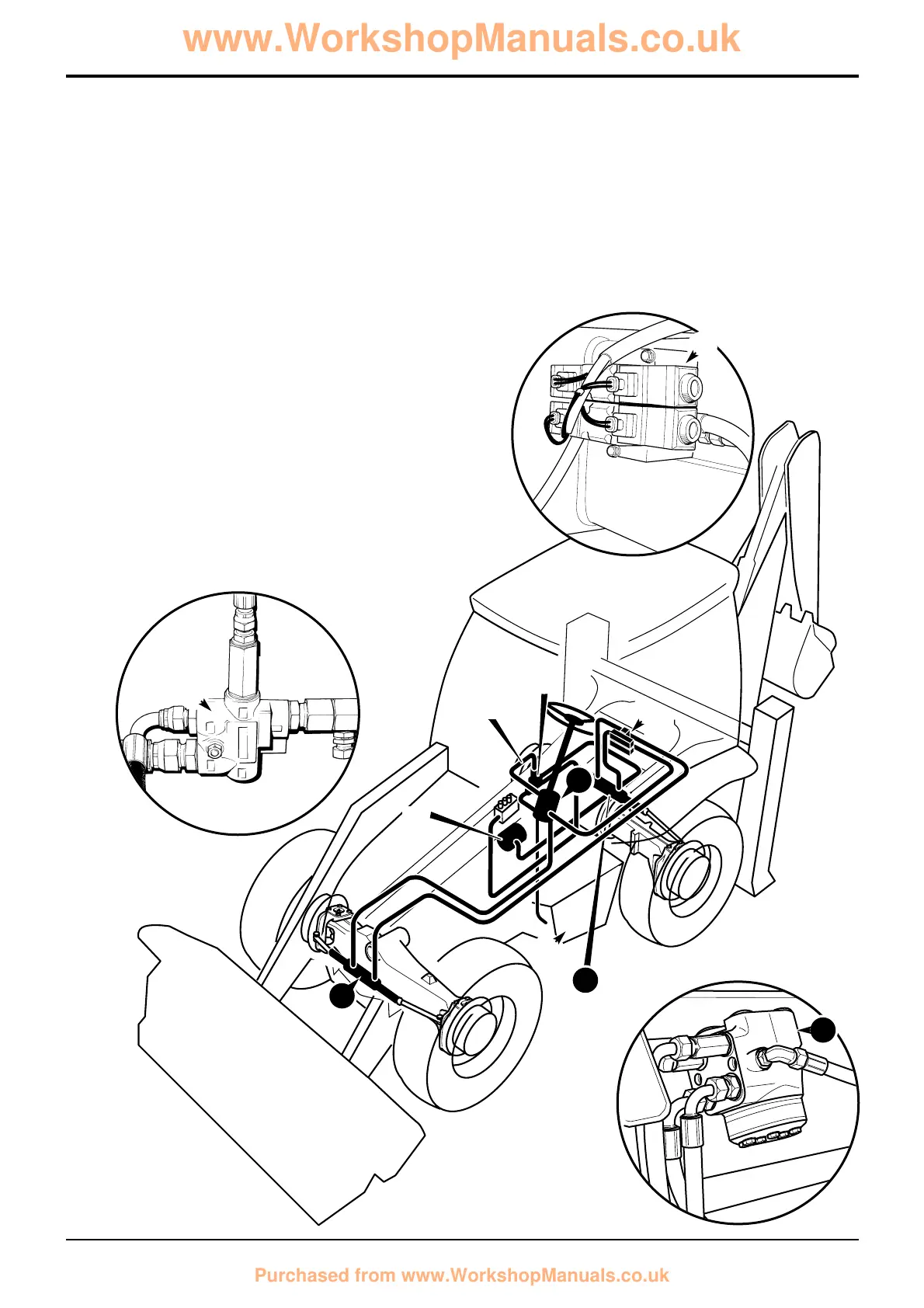
4 Wheel Steer Machines
Hydraulic Operation
The main components of the steering system are the priority
valve 7, load sensing steer unit 42, hydraulic tank T, front
power track rod ram 10 and rear power track rod ram 11.
When the steering wheel is turned, a pressure demand is
sensed at the priority valve 7 via load sensing line LS.
Oil from the hydraulic pump P2 is then distributed via the
priority valve to the steer unit 42.
When left turn is selected, oil is distributed from steer unit 42
to the rear power track rod ram 11 via the steer mode
control valve 8. When right turn is selected, oil is delivered
directly to the front power track rod ram 10.
When the steering lock is held, the pressure signal LS
ceases, flow from the hydraulic pump is now distributed to
the main hydraulic circuit via the priority valve 7.
Maximum steering system pressure is controlled by a relief
valve located in the steering unit 42.
LS
7
8
7
T
42
42
10
11
 Loading...