24 - 4
EXAMPLE - Boom Ram110 x 60
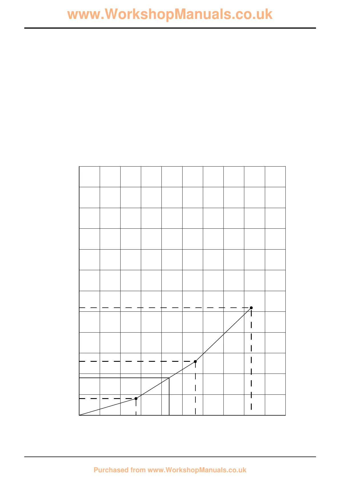
1 Using the figures given in the table on page 3, plot a
graph for the ram to be tested.
2 Check the pressure in the ram (induced by the applied
load). In this example the pressure on the gauge reads
107 bar; 1500 lb/in
2
.
3 Draw a vertical line from the pressure reading to the
plotted graph line. Where the vertical line intercepts the
graph line, draw a horizontal line and read the permitted
ram displacement. In this example the permitted
maximum displacement is 18 mm.
Note: A blank graph is provided on the next page,
photocopy and use as required.
Section E
Hydraulics
9803/3280
Section E
24 - 4
Issue 1
Service Procedures

 Loading...