23 - 6
Section E Hydraulics
9803/3280
Section E
23 - 6
Issue 1
Service Procedures
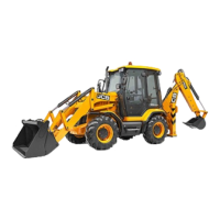
4 Install the A.R.V. sub-assembly into setting body 2.
Make sure that the adjusting pin 3 correctly locates in
adjusting screw 9.
Make sure that the lock nut 10 correctly locates in the
setting body socket - the anti-cavitation cone should
still be closed, as shown at B.
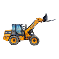
5 Install the A.R.V. sub-assembly and setting body into
test block 1. Make sure that the assembly is installed in
the port marked 'RV' (relief valve).
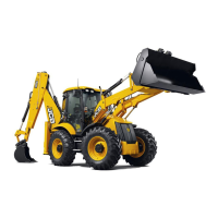
6 Connect a hydraulic hand pump to port 'P' (pump) of
the test block 1. Make sure that the hand pump is filled
with JCB Hydraulic fluid.
Connect a 0 to 400 bar (0 to 6000 lbf/in
2
) pressure test
gauge to port 'G' (gauge) of the test block 1.
Port 'T' (tank) can be left open when using a hydraulic
hand pump.
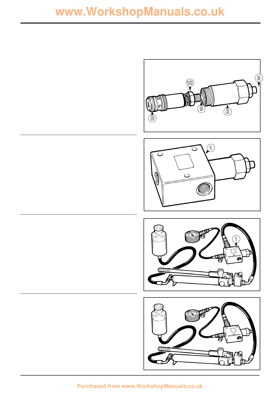
7 Raise the pressure at the valve inlet using the hydraulic
hand pump, when the A.R.V. 'cracks' and oil escapes
from the port marked 'T' the pressure gauge will
indicate the A.R.V. setting.
If the A.R.V. setting is correct, move to step 12.
If the A.R.V. setting is not correct, move to step 8.
Auxiliary Relief Valves - Using Hand Pump
S162570D
S162570E
S162570F
S162570F
B
9
2
3
0
1
1
 Loading...