Home
JUKI
Sewing Machine
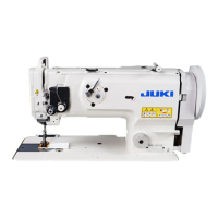
DNU-1541
JUKI DNU-1541 Engineer's Manual
4
of 1
of 1 rating
58 pages
Give review
Manual
Specs
To Next Page
To Next Page
Loading...
R
ENGINEER’S MANUAL
29353505
No.E349-01
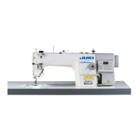
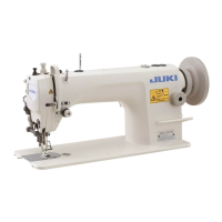
1-Needle, Unison Feed, Lockstitch Machine
DNU-1541
1-Needle, Unison Feed, Lockstitch Machine
(with Safety Mechanism)
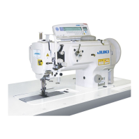
DNU-1541S
1-Needle, Unison Feed, Lockstitch Machine
(with Automatic Thread Trimmer)
DNU-1541-7
2
Table of Contents
Default Chapter
3
Table of Contents
3
Installation of the Optional Parts
3
Specifications
3
Standard Adjustment
3
Specifications
5
Standard Adjustment
6
Needle Entry Position
6
Longitudinal Position of the Feed Dog
6
Lateral Position of the Feed Dog
8
Height of the Feed Dog
8
Adjusting the Opener (DNU-1541S)
10
Needle-To-Hook Timing
10
Lift of the Presser Foot
12
Hand Lifter
12
Knee Lifter
12
Feed Motion
14
Amount of Alternate Vertical Movement
14
Alternate Momentum
16
Feed Cam Timing
16
Horizontal Feed Cam Timing
16
Top Feed Cam Timing
18
Needle Sway (Optional Selection Only of DNU-1541-7)
20
Stitch Length of Normal/Reverse Feed
20
Balancer (DNU-1541, DNU-1541S)
22
Position of the Reverse Feed Control Lever
24
Safety Clutch (DNU-1541S)
26
Lubrication
26
Standard Adjustment of Thread Trimmer Components (Dnu-1541-7)
28
Thread Trimmer Device
28
Cam Follower
28
Solenoid Arm
28
Thread Trimmer Cam Timing
30
Rotary Knife and Fixed Knife
30
Alternate Vertical Dial
32
Adapting SC-380 to DNU-1541-7
34
Installation of the Optional Parts
36
Automatic Reverse Feed Device
36
Removing the Window Plate (List of the Parts to be Removed)
36
Removing the Reverse Feed Control Lever (List of the Parts to be Removed)
36
Installing the Reverse Feed Link Hinge Screw (List A)
36
Installing the Reverse Feed Control Lever1. Reverse Feed Control Lever (List B)
37
Installing the Automatic Reverse Feed Device (List C)
37
Installing the Touch-Back Switch (List D)
38
Installing the Pneumatic Components (List E)
38
Parts List
38
Automatic Presser Foot Lifter
40
Installing the Automatic Presser Foot Lifter (List A)
40
Installing the Pneumatic Device Components
41
Parts List
42
Installing the DL Device
44
When Installing the DL Device to DNU-1541-7 after Set-Up of the Machine (List A)
44
Installing the Pneumatic Device Components (List B)
44
Installing the 5-Step Switch (List C)
44
Parts List
45
Portion to Which Locktite Is Applied
46
Selective Parts and Consumable Parts
47
Engraved Marker Dots on the Handwheel
48
Lubrication Route Diagram
48
Pneumatic Piping
49
Machine Head Wiring (with Thread Trimmer Only)
50
Connector Coming from the Machine Head
50
Connector Coming from the Pneumatic Device
51
Connector Coming from the Relay Cable (Inserting Side to the Control Box)
52
Table of Troubles and Corrective Measures
53
With Reagard to Sewing
53
With Regard to Lubrication
54
With Regard to Thread Trimming
55
Others
56
Drawing of the Table
57
Other manuals for JUKI DNU-1541
Instruction Manual
28 pages
Specifications
4 pages
4
Based on 1 rating
Ask a question
Give review
Questions and Answers:
Need help?
Do you have a question about the JUKI DNU-1541 and is the answer not in the manual?
Ask a question
JUKI DNU-1541 Specifications
General
Brand
JUKI
Model
DNU-1541
Category
Sewing Machine
Language
English
Related product manuals
JUKI DNU-1541S
28 pages
JUKI DNU-1541-7
33 pages
JUKI DNU-261H
272 pages
JUKI DNU-241H-7
12 pages
JUKI DDL 555
15 pages
JUKI DDL-8700
40 pages
JUKI DU-141NH
272 pages
JUKI DDL-900A
52 pages
JUKI DDL-900B
54 pages
JUKI DU-1181N
46 pages
JUKI DDL-5550N
48 pages
JUKI DDL-9000B
26 pages