− 40 −
(3) Installing the DL device
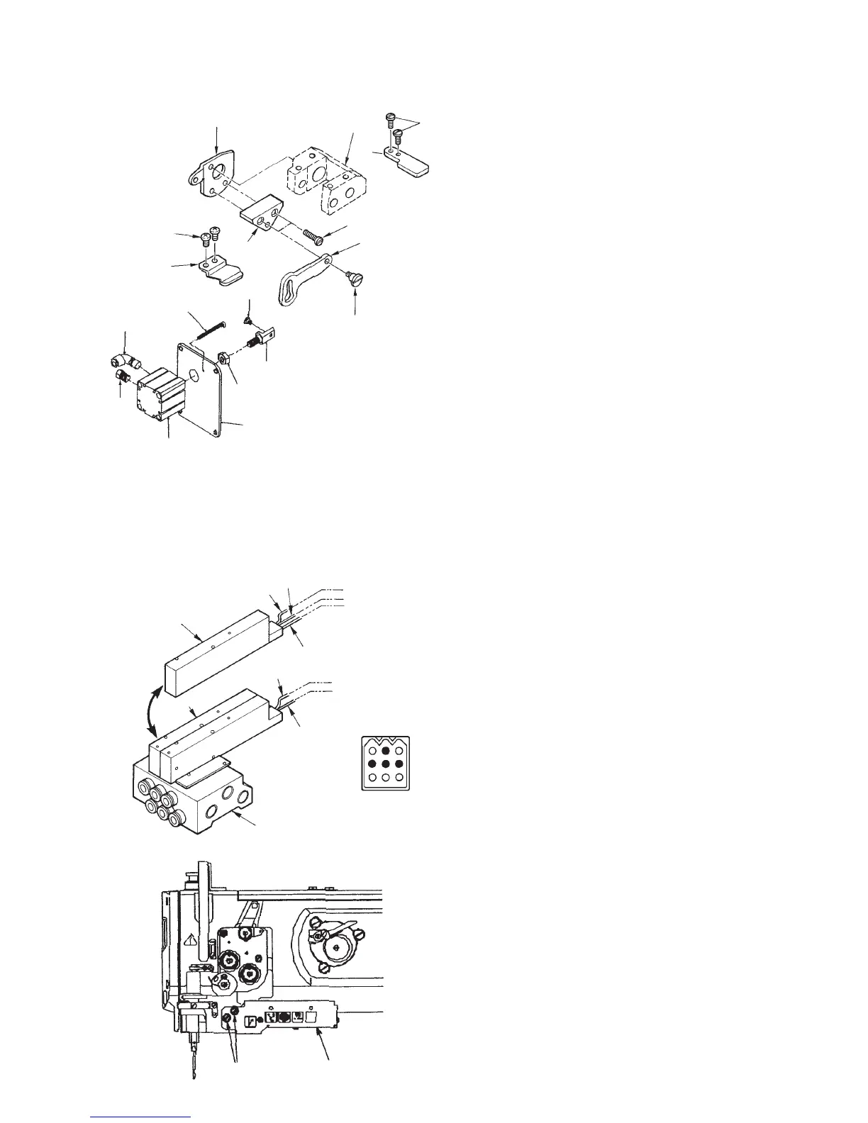
1) When installing the DL device to DNU-1541-7 after set-up of the machine (List A)
1. Remove the window plate E located on the anti-
operator’s side of the machine arm. (Removing
parts list)
2. Attach elbow 2, muffler 3, cylinder connecting
screw 4, alternate vertical link hinge screw 5 and
nut 6 to jig cylinder 1.
3. Attach the cylinder which has been assembled at
the above step 2. to window plate F 7 and tighten
it with jig cylinder setscrew 8.
4. Remove the top feed stopper plate A attached to
alternate vertical change base !6 and attach top
feed stopper plate B 9.
5. Tighten alternate vertical link spacer !0 to top feed
stopper plate B 9 with setscrew !1 and tighten
alternate vertical link !2 with hinge screw !3.
6. Remove the top feed stopper plate attached to the
machine arm and tighten top feed stopper plate !4
with setscrew !5.
7. Tighten alternate vertical link support !7 to the
machine arm with setscrews !8.
8. When installing window plate F 7, enter alternate
vertical link hinge screw 5 to the hole of alternate
vertical link !2 and attach it to the machine arm.
9. Install the pneumatic device components (asm.).
10. Install the 5-step switch (asm.) and connect the relay cord with it.
11. Insert the air hose and check the operation.
• When actuating DL, the amount of the alternate vertical movement becomes maximum and the walking
foot goes up.
3) Installing the 5-step switch (List C)
1. Install 5-step switch 1 with 5-step switch setscrews 2.
1
2
2) Installing the pneumatic device components (List B)
1. Replace manifold a attached to the solenoid valve B
being used now with solenoid valve D 1.
2. Caulk the pin terminal, male and female, to the top
end of the cord.
3. Insert the pin terminal, male and female, into the
plug CN1.
• Insert it after making sure of the inserting position.
4. Connect the air hose with solenoid valve B.
1
2
3
4
5
6
7
8
9
!0
!1
!2
!3
!6
!4
!5
CN1
1
4
7
3
6
9
!8
!7
1
a
Red
Black
White
Red
Black
Solenoid valve B
CN1-1
CN1-4
CN1-2
CN1-5
CN1-6
 Loading...