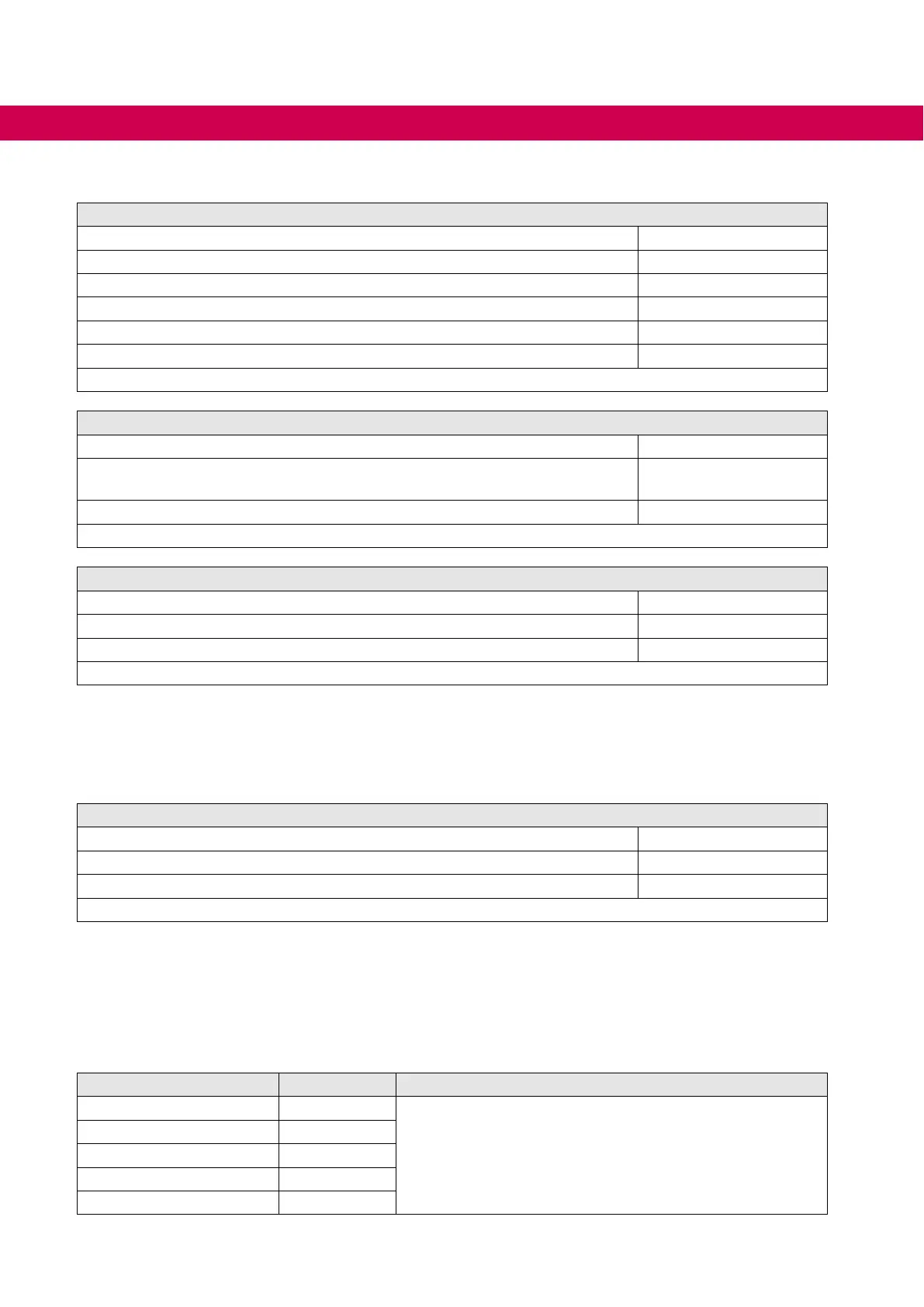
3.3.3 Voltage and frequency data
Input voltage and frequencies
Rated input voltage U
N / V 400
Rated input voltage UL U
N_UL / V 480
Input voltage range U
in / V 184…550
Mains phases 3
Mains frequency f
N / Hz 50 / 60
Mains frequency tolerance ±f
N / Hz ±2
Table 9: Input voltage and frequencies
Input voltage for DC operation
Rated input voltage DC U
N_dc / V 565
Rated input voltage DC UL U
N_dc_UL
/ V
672
Input voltage range DC U
in_dc / V 260…750 ±0
Table 10: Input voltage for DC operation
Output voltage and frequencies
Output voltage at AC supply
1)
Uout / V 3 x 0…Uin
Output voltage at DC supply
1)
Uout_dc / V 3 x 0…Uin_dc/√2
Output frequency
2)
fout / Hz 0…599
Table 11: Output voltage and frequencies
1)
The voltage to the motor is dependent on the actual input voltage and the control method (=>
“Example for the calculation of the motor voltage”).
2)
The output frequency is to be limited in such a way that it does not exceed 1/10 of the switching
frequency. Units with higher max. output frequency are subject to export restrictions and are only
available on request.
DC switching level
DC switch-off level „Error! Underpotential“
UUP_dc / V 240
DC switching level braking resistor
1)
UB_dc / V 780
DC switch-off level „Error! Overpotential“
UOP_dc / V 840
Table 12: DC switching level
1)
The DC switching level for the braking transistor is adjustable. The default value is the value spec-
ied in the table.
3.3.3.1 Example for the calculation of the motor voltage
The motor voltage for dimensioning of the drive is depending on the used components.
The mains voltage reduces according to the following table:
Components Reduction / % Example
Mains choke U
k 4
Closed-loop drive converter with mains- and motor choke at
non-rigid supply system:
400 V mains voltage - 15 % = 340 V motor voltage
Drive converter open-loop 4
Drive converter closed-loop 8
Motor choke U
k 1
Non-rigid supply system 2
30
UNIT DATA

 Loading...


