48
CONNECTION OF THE POWER UNIT
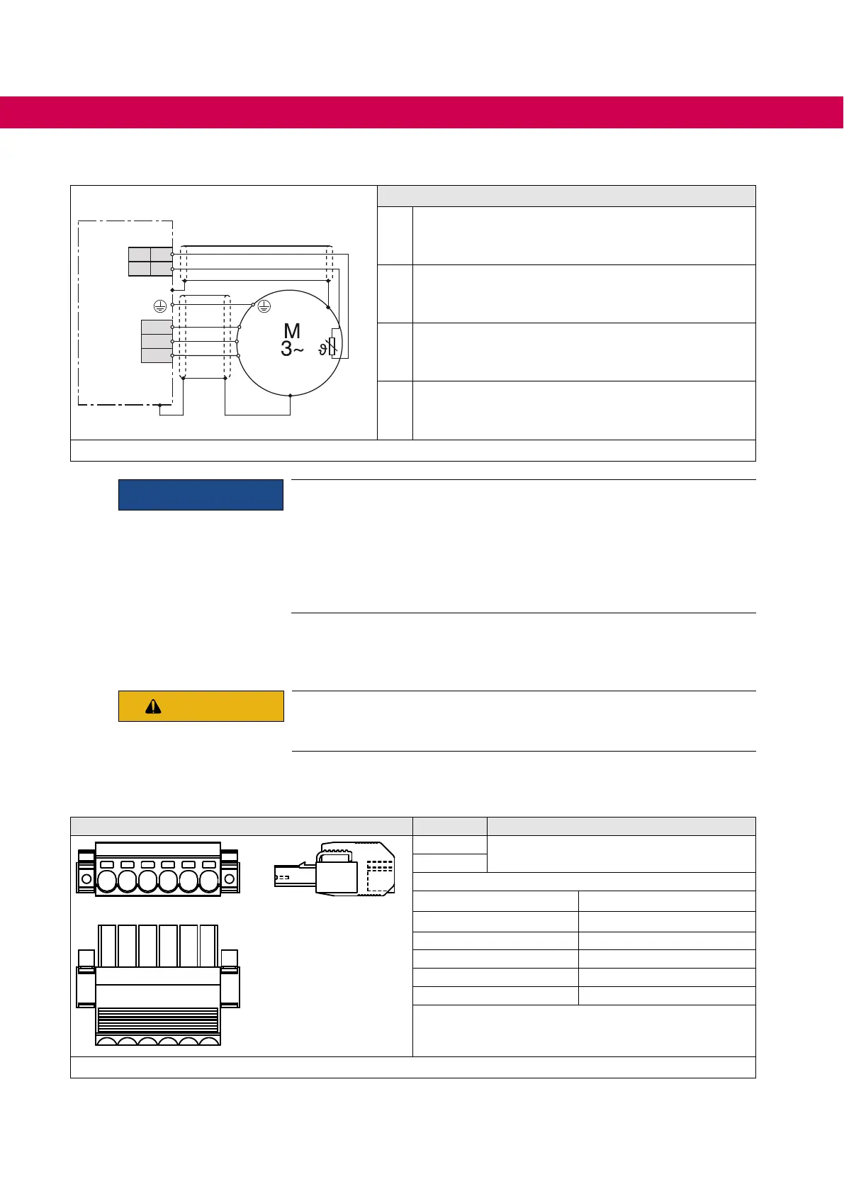
4.2.5.8 Wiring of the motor
U
V
W
U
V
W
5
6
X1C
X1A
➀ ➁ ➂
9
10
Control
P A/K
④
Legend
①
KEB COMBIVERT
②
Apply motor cable, shielding on both sides over a
large surface on the function earth (screening shield
or mounting plate)
③
Three-phase motor
④
Temperature monitoring (optional)
=> Instructions for use „Control unit“
Figure 17: Wiring of the motor
NOTICE
Connection of the temperature monitoring
• Do not lay the connection cable of the motor temperature detection
(also shielded) together with the control cable !
• The connection cable of the temperature detection inside the motor
cable is only permissible with additional shielding (double shielding) !
• The input of the temperature detection has basic isolation.
4.2.6 Connection of a braking resistor
CAUTION
Not fall below the minimum braking resistor value! Falling below
the minimum braking resistor value destroys the braking transistor of
the drive converter.
4.2.6.1 Terminal strip X1B connection braking resistor
X1B Name Function
R -- ++ U V W
++
Connection braking resistor
R
Type Push-In spring connection
Screwdriver blade 08 x 4.5
Stripping length 12 mm
Wire cross-section AWG 24-8
without wire-end ferrule 0.5...10 mm²
with wire-end ferrule 1.5...6 mm²
Figure 18: Terminal block X1B Connection of a braking resistor

 Loading...


