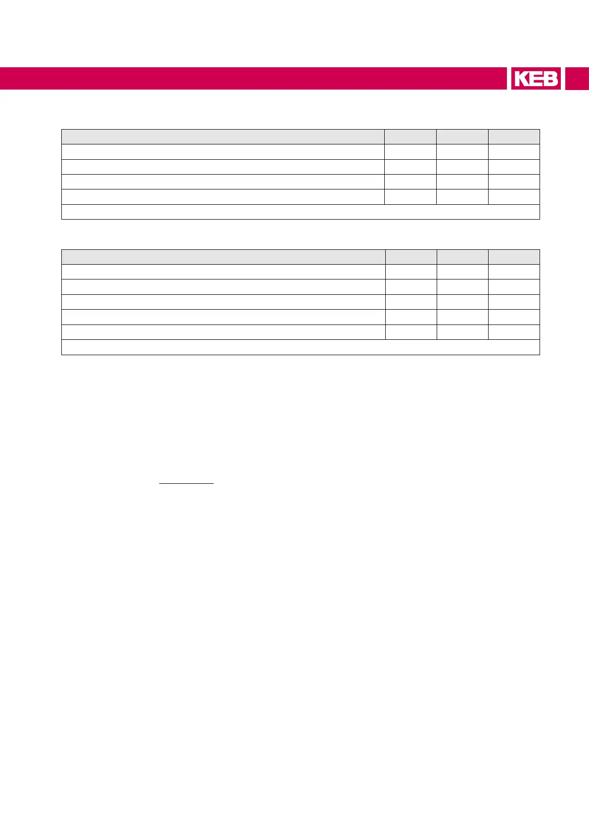
3.3.4 Input and output currents / overload
Unit size 12 13 14
Rated input current @ U
N = 400V IIN / A 13 17 21
Rated input current UL @ U
N _UL = 480V Iin_UL / A 11 15 18
Rated input current DC @ U
N_dc = 565V
1)
Iin_dc / A 16 20 26
Rated input current DC UL @ U
N_UL_dc = 680V
1)
Iin_dc_UL / A 13 19 22
Table 13: Input currents
1)
The values resulting from rated operation with B6 rectier circuit and mains choke 4% UK.
Unit size 12 13 14
Rated output current @ U
N = 400V IN / A 9.5 12 16.5
Rated output current UL @ U
N _UL = 480V IN_UL / A 7.9 10 14
Overload current (60s)
1)
I60s / % 200 200 150
Overload current (3s)
1)
I3s / % 250 250 180
Overcurrent
1)
IOC / % 300 300 216
Table 14: Output currents
1)
The values refer in % to the rated output current IN.
3.3.4.1 Overload characteristic (OL)
All COMBIVERT S6 can be operated time-limited at rated switching frequency even in
overload.Further information can be found in the diagrams “Turn-off time depending on
the overload at unit size 12 and 13” and “Turn-off time depending on the overload at unit
size 14”.
Restrictions:
• The thermal design of the heat sink is based on the rated current and the maximum
surrounding temperature. At high surrounding temperatures and/or high heat sink
temperatures (for example, by preceding utilization nearby 100%), the drive con-
verter can change to overtemperature error before triggering the protective function
OL.
• At low output frequencies or switching frequencies higher than the rated switching
frequency, the maximum current (I0Hz/I6Hz) can be exceeded before and the error
OL2 can be triggered (see also chapter "Maximum current (OL2)“).
On exceeding a load of 105% the overload integrator starts. When falling below the in-
tegrator counts backwards. If the integrator achieves the overload characteristic, „Error!
Overload“ is triggered.
After a cooling period the message „no ERROR overload“ is displayed. The error can be
reset now. The drive converter must remain switched on during the cooling down phase.
31
UNIT DATA

 Loading...


