4 Installation and Connection
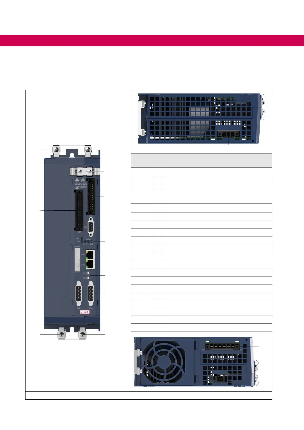
4.1 Overview of the COMBIVERT S6
PE PE
X2B
X2A
X4A
LED1...5
X4B
X4C
X3A
PE
PE
X3B
X2Z
S1/S2
X1A
Representation by the example of an APPLICATION
control board
X1A Mains input
X1B
Motor output /
Connection for braking resistor
X1C
Temperature monitoring;
brake control
X2Z Strain relief
X2A
1)
Control terminal strip
X2B
1)
Safety functions / 24 Vdc supply
X3A
1)
Encoder interface channel A
X3B
1)
Encoder interface channel B
X4A
1)
Diagnosis interface
X4B
1)
Fieldbus interface (in)
X4C
1)
Fieldbus interface (out)
PE Protection-/functional earth
S1/S2
1)
Rotary coding switch
FS ST
1)
Safety status
VCC
1)
Voltage supply
NET ST
1)
Fieldbus state
DEV ST
1)
Drive converter state
OPT
1)
optional
1) Is described in the installation manual of the control board.
X1B
X1C
Figure 9: S6 overview
40
OVERVIEW OF THE COMBIVERT S6

 Loading...


