4-4 Troubleshooting
Principles of operation
The following information is provided to support the troubleshooting tests and procedures
covered in this section of the manual. Refer to the following block diagrams:
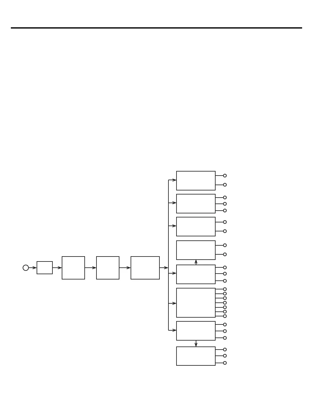
Figure 4-1 — Power supply block diagram
Figure 4-2 — Digital circuitry block diagram
Figure 4-3 — Simplified schematic of analog circuitry
Power supply
The following information provides some basic circuit theory that can be used as an aid to
troubleshoot the power supply. A block diagram of the power supply is shown inFigure 4-1.
Figure 4-1
Power supply block diagram
CR315
C320, C322
U304
CR312, CR314
C317, C318
Q304
CR316, CR317
C325
U305
U301
CR301 - CR303
C302, C303
VR304
CR304 - CR309
C305 - C308
Q302, Q303
CR310
C311, C312
U302. U303
C314, C316
+5VD
D Common
-6VD
D Common
+37V
D Common
+5V, +5V OPTO
A Common
+7V
A Common
+23V
+7V
-7V
A Common
-7V
-29V
+18V
A Common
-18V
+15V
A Common
-15V
Fuse
Power
Switch
Line
Voltage
Switch
Power
Transformer
T300
-5VD
+29V
-20V
 Loading...


