Troubleshooting 4-13
Analog circuit checks
Table 4-5 summarizes checks for the analog circuits. These tests involve applying specific test
voltages to the channel 1 input terminals and measuring voltages at the indicated test points. See
Figure 1-1 in Section 1 for DC voltage input test connection.
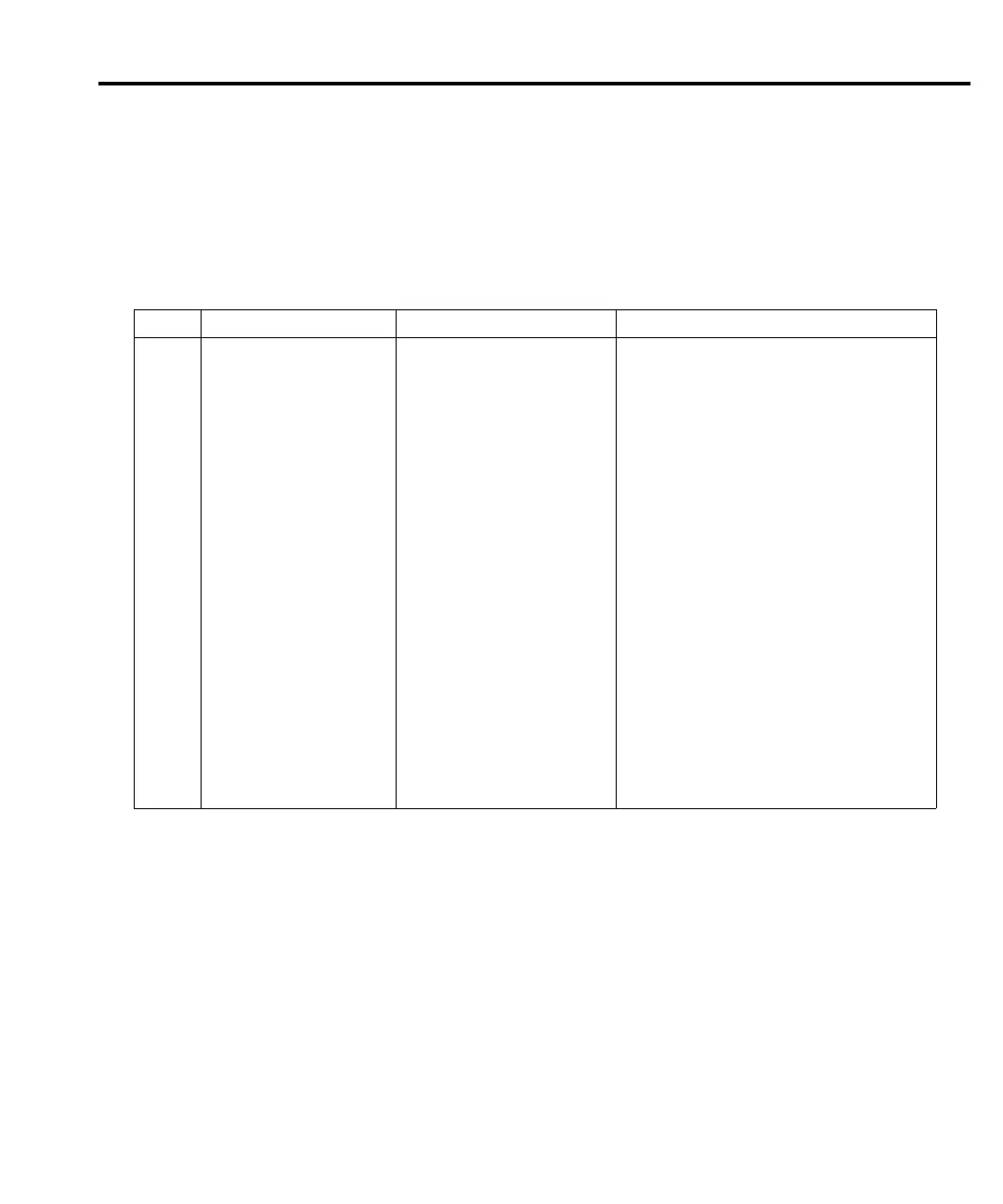
Table 4-5
Analog circuit checks
Step Item/component Required condition Remarks
1 Function DCV1 Use DCV1 for measurements.
2 Input connections CH1 HI and LO Connect voltage source to CH1.
3 Measurement range 100V Select 100V range.
4 Input voltage 100V Apply 100V to CH1 input.
5 U601 pin 6 +1V Buffer output.
6 TP652 +10V Multiplexer output to A/D.
7 Measurement range 10V Select 10V range.
8 Input voltage +10V Apply 10V to CH1 input.
9 TP651 +10V Preamp output.
10 TP652 +10V Multiplexer output to A/D.
11 Measurement range 1V Select 1V range.
12 Input voltage +1V Apply 1V to CH1 input.
13 TP651 +1V Preamp output.
14 TP652 +10V Multiplexer output to A/D.
15 Measurement range 100mV Select 100mV range.
16 Input voltage +100mV Apply 100mV to CH1 input.
17 TP651 +100mV Preamp output.
18 TP652 +10V Multiplexer output to A/D.
19 Measurement range 10mV Select 10mV range.
20 Input voltage +10mV Apply 10mV to CH1 input.
21 TP651 +1V Preamp output.
22 TP652 +10V Multiplexer output to A/D.
Notes: 1. Before testing, disable autozero by sending the following command over the remote interface:
:SYST:AZERO:STAT OFF.
2. All voltage measurements referenced to TP303.
 Loading...


