Troubleshooting 4-5
AC power is applied to the AC power module receptacle. Power is routed through the line
fuse and line voltage selection switch of the power module to the power transformer. The power
transformer has several secondary windings for the various supplies.
AC voltage for the display filaments is taken from a power transformer secondary at F1 and
F2, and then routed to the display board.
Each DC supply uses a rectifier and a capacitive filter, and many supplies use an IC regulator
or transistors. The various components are shown inFigure 4-1.
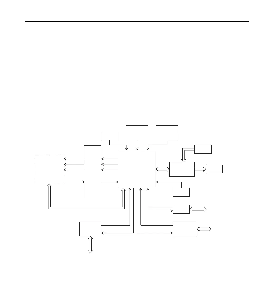
Display board
Display board components are shown in the digital circuitry block diagram in Figure 4-2.
Figure 4-2
Digital circuitry block diagram
Analog
Circuitry
(See Figure 4-3)
XADTX
XADCLK
XADTS
XADRX
O
P
T
O
I
S
O
U114,
U115,
U116
NVRAM
U112
ROM
U102, U103
RAM
U104, U105
Keypad
Display
DS401
Display Board
Controller
U401
XTAL
Y101
RS-232
U110
RS232
Port
IN
OUT
Data IN
Data OUT
GPIB
U106, U108,
U109
IEEE-488
Bus
Trigger
Link
TRIG IN
TRIG OUT
Trigger
U113
ADTX
ADCLK
ADTS
ADRXB
68306
µP
U101
 Loading...


