4-14 Troubleshooting
Analog signal switching states
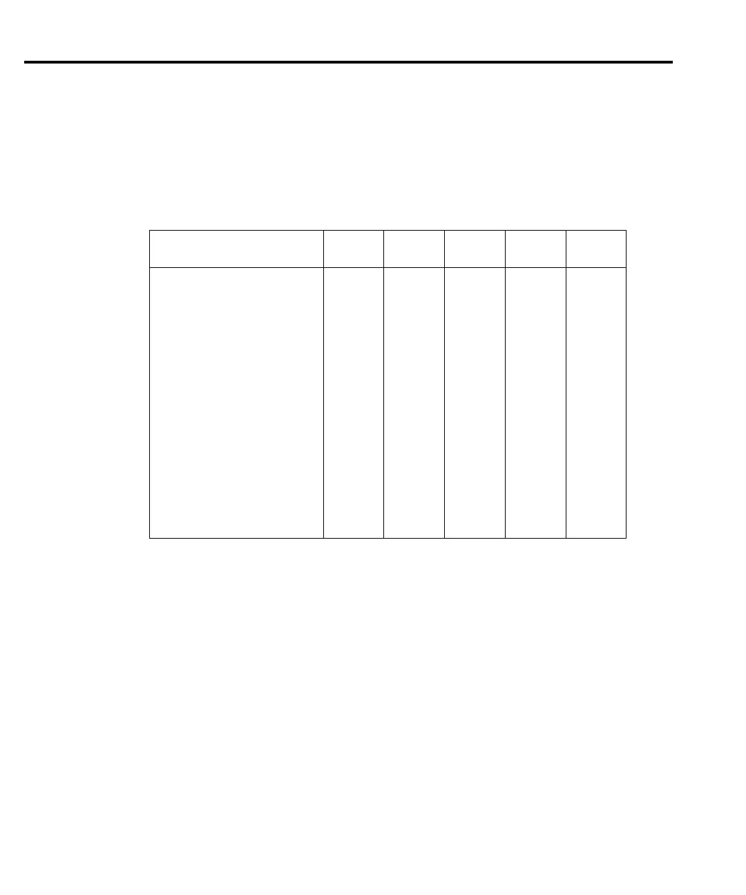
Table 4-6 and Table 4-7 provide switching states of the various ICs and transistors for the
basic measurement functions and ranges. These tables can be used to assist in tracing an analog
signal from the channel 1 and channel 2 inputs to the A/D multiplexer.
Table 4-6
Signal multiplexing gain switching
Function and Range
U626
(Signal)
U632
Pin 1
U632
Pin 8
U632
Pin 9
Gain
DCV1:
10mV S4 Off Off On X10
100mV S4 Off On Off X100
1V S4 Off Off On X10
10V S4 On Off Off X1
100V S3 Off Off On X10
DCV2:
100mV S4, S7 Off On Off X100
1V S4, S7 Off Off On X10
10V S4, S7 On Off Off X1
DCV2 (LQ MODE ON)*
100mV S3, S7 Off On Off X100
1V S3, S7 Off Off On X10
10V S3, S7 On Off Off X1
*Send the following remote command to enable. :SENS:VOLT:CHAN2:LQM ON.
 Loading...


